This thread has been locked.

If you have a related question, please click the "Ask a related question" button in the top right corner. The newly created question will be automatically linked to this question.

BQ24610: Typical Application circuit doesn't works

Part Number: BQ24610

Hi TI Support team,

Please help me,

I am on testing BQ24610 chip with Typical Application circuit., 
There is just small modification, I just remove the BATDRV FET and SYSTEM Line, because I just want use this IC just for charging battery.

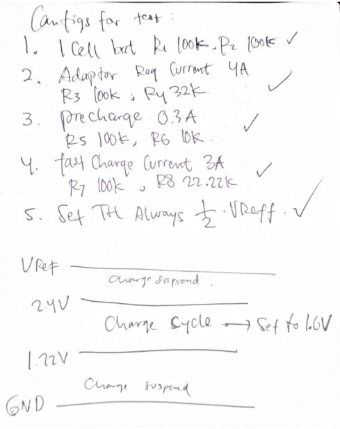
I am configure the circuit using "bqstroller calculation tools_V1.5"

I short TTC to Ground to disable it.

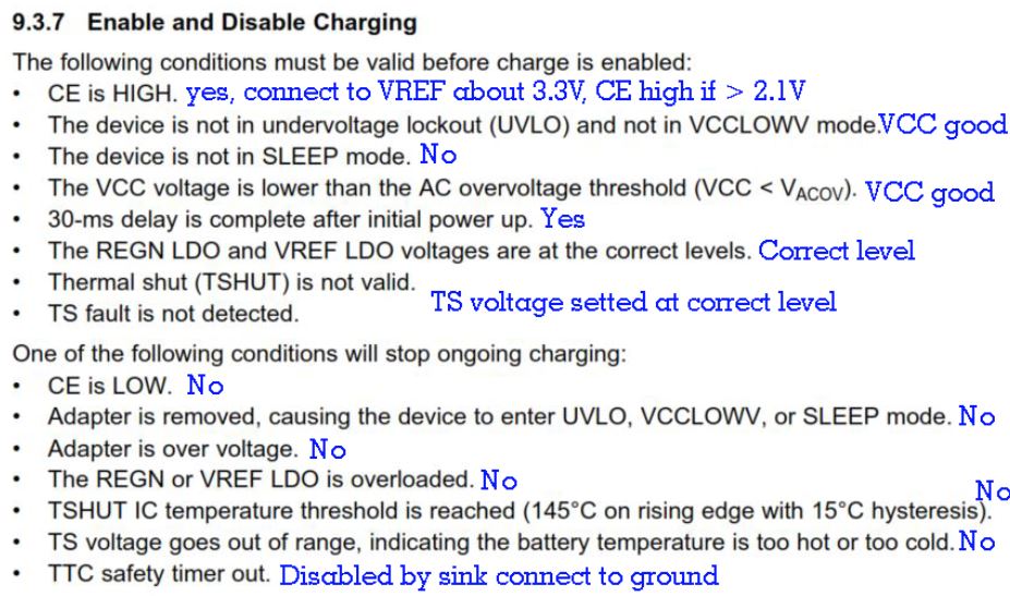
I want to verify these :

1. Typical Application circuit is for AC input or DC input ? I bit confuse because of the name ACDRV , ACP, ACN , etc. currently I test with 19VDC input supply

2. I wont use Thermistor, so with Voltage divider I set TS pin about 1.6V, is it okay ?

3. I wont use BATDRV, so I am not put BATFET circuit, is it okay ?

4. is it must put Diode zener 7.5V from ACDRV pin to VCC pin ?

5. is it must put Diode from ground to PH pin ?


I think I already meet all requirements to enter charging cycle, but 2 STATs LED always turn OFF.

  • Hi Ghild,

      By Typical Application schematic, are you testing on the BQ24610 evaluation module or your own board? If it is your own board, can you share with me the schematics?

    For your questions:

    1. 19VDC input is fine
    2. Setting TS to 50% is fine as it is within the VLTF and VHTF thresholds
    3. Yes, when disconnecting BATFET float BATDRV pin and disconnect other components from that pin
    4. No, Zener diode is not required from ACDRV to VCC
    5. No diode from GND to PH is not required.
  • Hi Kedar,

    Thanks for your answers.,

    From your answer, I know there is something wrong with my chip , broken or not connect properly to PCB.,

    There is something I need know about STAT indicator:

    1. if the chip supplied by valid VCC, more than 4.1V, the PG LED will turn ON, and STAT1 STAT2 will still OFF because I am not connect battery, yes ?

    2. how about after I connect battery but CE still low ?

    3. what indicator will turn ON if battery connect but at full condition ?

    4. how about if both STAT1 and STAT1 turn on ? 


    There is something I need know about Chip Assembly:

    1. is that chip will broken at certain temp level ? I assembly use blower.

    2. do you have any suggestion how to assembly the chip properly ?


    Kedar Manishankar said:

      By Typical Application schematic, are you testing on the BQ24610 evaluation module or your own board? If it is your own board, can you share with me the schematics?

    I am testing with my own board, which follow the Typical Application schematic , I am already order EVM board for help me to verify this issue.

  • Hi Kedar, 

    I am want ask one more question.,
    My board can charge now, but when the battery already reach 4.2V why it not stop  ?
    should be Stat1 turn off and stat2 turn on, indicate that charging process is finished , right ?

  • Hi Ghild,

       Please verify the resistor divider network calculations on VFB as this is used to set the charge regulation voltage. Depending on the accuracy of your resistors it is possible there could be some variation, but the charger's accuracy itself to regulate charge current is quite low and it is accurate. You are correct about STAT pin operation when charge is terminated.