This thread has been locked.

If you have a related question, please click the "Ask a related question" button in the top right corner. The newly created question will be automatically linked to this question.

TPS43060: TPS43060 FEEDBACK and DUTY CYCLE ISSUE

Part Number: TPS43060
Other Parts Discussed in Thread: TPA3255,

Dear TI team

Unrelated but possibly of interest to those who have assisted me with my TPA3255 PROJECT.. I managed to get it going!  Very happy now. (Decoupling + a correct Reset chip, and using a PCB which did not have some obscure issue with it,  did the job)

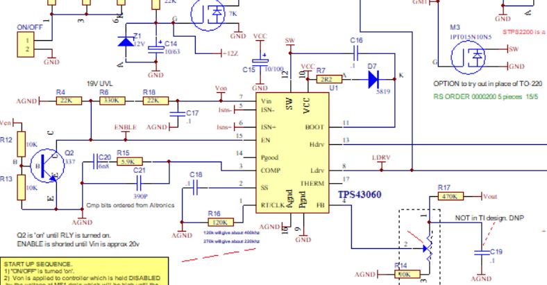
DC-DC converter.  TPS43060  is where my current challenge resides.

I've put together a circuit pretty much the same as in the 'Applications' recommendation for the 10-38v in/  40v/3a output in the Data Sheet.

When I turned it on, I find what seems like a 'minimum' pulse width/duty cycle, and I cannot adjust it with my feedback trimpot.

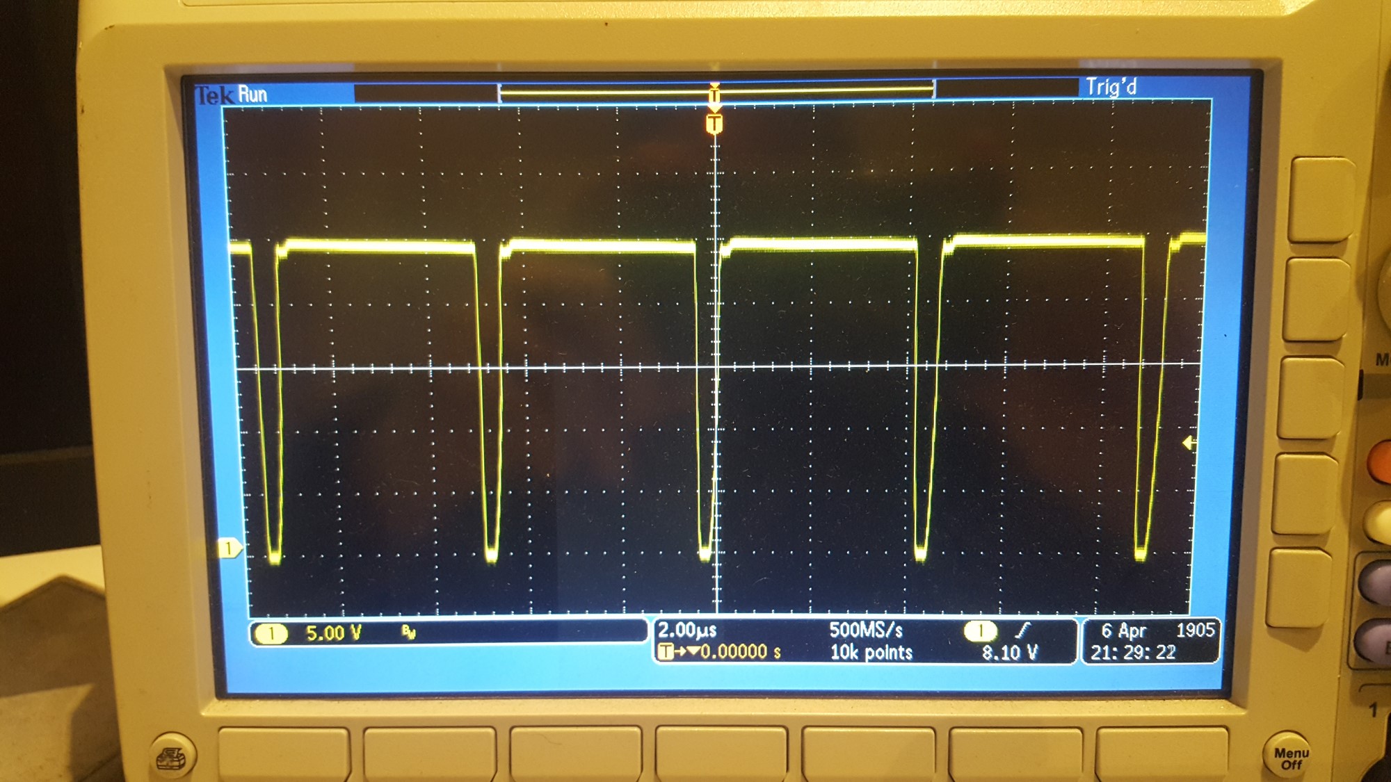
I'm trying to produce 50v (even @ 1 amp) but as the image shows (of my drain waveform) the drain voltage pulses, but does not, or only barely exceeds the DC supply voltage.

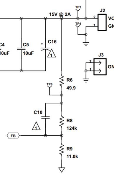
So, I cannot reach the 1.22v for the feedback voltage, rather, it's about .3v to .4.  When this is the case, I would normally expect the Duty cycle to crank out to whatever level will  produce 

sufficient output voltage to achieve the right feedback.  But... *nothing*... it' just sits as you see it.  (22v Vin)

Are there any internal workings which might impact this?

Pay no attention to the specific mosfets shown here, I know the issues and I'm simply seeking to get the CCT working, then I'll optimize with low Cgs FETS.

Any perspective would be welcome.
Regards
Julian de Ross


  • Hi Julian de Ross

    experts supporting this device is out of office. they will reply you next week.

  • Hi Julian,

    Thank you for using the TPS43060.  It seems the circuit trips peak current limit, so your FB or COMP will not affect the duty cycle.  Please double check COMP voltage, which should stay high in this case.  

    If it is really the peak current limit, please check the following:

    (1) Current sense resistor:  is a wrong part used, or is it soldered correctly? 

    (2) Current sense resistor connections to the ISN+ and ISN- pins: please monitor the voltage directly across these two IC pins.  

    (3) Inductor:  is it rated to support the peak current during normal operation?

    (4) Please check against the TPS43060 Design Calculator at the following link for component selections, especially the Rsn and inductor parameters. Make corrections accordingly.

    www.ti.com/.../slvc471

    Thanks,

    Youhao Xi, Applications Engineering

  • Thanks for that

    I'll look at each issue you mentioned.
    I'll be asking a sort of related question about another device, but it probably applies to this one as well.

    If the peak current limit is not triggering,  I'm wondering about the feedback voltage and how this is processed in the chip.
    For example...In the application note of the data sheet for the 43060,  (as per the image attached)  

    I calculated the feedback voltage at 15v vout.  Using the resistors shown, it comes to .8923v
    This seems to suggest the chip is very tight in it's processing of feedback voltage, which is fine, but if say I wanted to adjust the output with a trim pot , will it follow by trying to develop that same voltage into the feedback pin and then remain stable (following load fluctuations of course)
    Am I right in understanding that the feedback loop will adjust the duty cycle to maintain an output voltage which produces the f/b voltage I calculated?

    Thanks

    J


  • Hi Julian,

    You are right that the feedback look will automatically adjust the duty cycle to regulate the output voltage to the setting point by the resistor divider.  This is based on the an assumption that the dc loop gain is high. However, if the peak current limit is tripped, it will take over and cut the duty cycle short, and you will not achieve the output regulation.

    In regulation, the FB voltage should 1.22V typical.  So, you calculation result of 0.8923 is not correct.

    Thanks,

    Youhao