This thread has been locked.

If you have a related question, please click the "Ask a related question" button in the top right corner. The newly created question will be automatically linked to this question.

UCC28950: Primary side vs Secondary side gate drive signal issue and low load switching noise

Part Number: UCC28950
Other Parts Discussed in Thread: UCC28951,

Hi Ti team,

Sorry for late response and don't know how to re-open the closed thread, so I create a new thread.

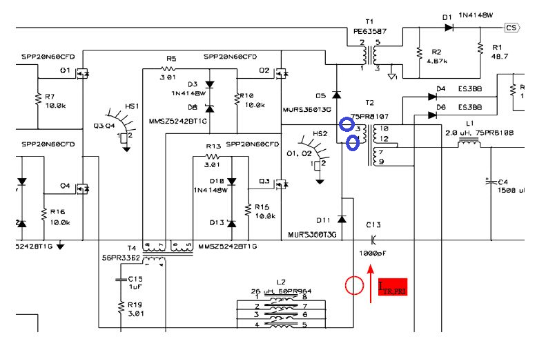
The picture shown how I measured primary side current, please see relates thread for info. Now try to fix it by increase secondary side GATE resistor to add more delay time for secondary side.

Actually TI can try it on your EVM at low load and see primary side transformer current.

Now another issue occurred, at low load <40Amp, how to solve the switching noise?

So please advise on below.

1. Please check your EVM at low load, see primary transformer current and advise how to fix it?

2. Switching noise at low load, how to solve this issue?

Thank you,

Suttichai

  • Hello Suttichai

    Thanks for re-posting - Just FYI: There is an 'Ask a Related Question' option given in the yellow panel at the bottom of the original post but let's use this new thread to continue this topic.

    Previously I had asked you to provide a sketch / schematic showing exactly where you have placed the current probe - the current at the red circle does not include the current through the clamp diodes (D5 and D11) so it ins not an accurate representation of the transformer primary current. If you want to measure the primary current you should move the probe to one of the locations shown in blue below. Alternatively you can use the CS signal from the current sensing transformer to see an accurate, scaled representation of the transformer primary current.

    I don't know what you mean by 'Switching noise at low load, how to solve this issue?'

    A few things to note -

    At light loads the UCC28950 (and UCC28951) drop into a burst mode. The repetition rate of the bursts can fall into the audio band causing audible noise due to magnetostriction effects in the magnetic components

    It is more difficult to maintain ZVS at lower currents. If the power stage loses ZVS then the dv/dt rates in the power stage will increase and you will get an increase in the EMI signature. You will also see an increase in noise coupled into the control circuit and this can cause erratic operation - unstable switching patterns for example.

    If you let me know the full load current and the current at which this switching noise starts to appear and also whether the problem is acoustic or electrical noise then I can give some advice.

    I would be careful about increasing the delays in the power stage - if the SR delays are too long then you can get high voltage spikes on the MOSFETs because the channel has not been turned on before the current in the device reverses.

    Regards

    Colin

  • Thanks Colin,

    I will try again and get more info for full load current and at which the switching noise starts to appear .

    Best regards,

    Suttichai

  • Hi Colin,

    More info:

    1. Full load current is 60A

    2. Light load which the switching noise starts is <15A.

    3. it's acoustic noise from switching transformer.

    Best regards,

    Suttichai

  • Hello Suttichai

    Please check a few things:

    Has the controller gone into burst mode when the noise starts - the easiest way to do this is to simply look at OUTx from the controller. It may be possible to reduce the threshold at which the system goes into burst mode.

    Is there a control loop instability that may be causing the oscillation - look for instability on Vout

    Check if there is an input filter oscillation - I think this is unlikely because the noise happens at lighter loads but it's worth eliminating it - the easiest way to do this is to short out the input differential mode filter.

    Are the two halves of the core well clamped together - normally glue on each of the faces or a metal clip or both is used. Are there other ways of holding the core halves together.

    Are the windings 'loose' - Vacuum varnish impregnation of the transformer is often used to prevent the windings from moving and causing the noise.

    If the transformer is mounted on a PCB is the Transformer to PCB mounting 'loose' - the PCB can act as a 'sounding board' and amplify any vibrations that are happening - you may need some dampening material between the transformer and the PCB or remove much of the PCB material under the transformer.

    Please let me know how you get on.

    Regards
    Colin

  • Thanks Colin for your suggestions,

    Let me check and will let you know for the result.

    Best regards,

    Suttichai

  • Hello Suttichai

    I'll leave this e2e thread open for another few days and then close it. We can always open a new thread if you have further questions

    Colin