This thread has been locked.

If you have a related question, please click the "Ask a related question" button in the top right corner. The newly created question will be automatically linked to this question.

LMZM33606EVM: About Synchronization operation

Part Number: LMZM33606EVM
Other Parts Discussed in Thread: LMZM33606, , LMZM33603

Hi,

Customers are evaluating LMZM33606 using EVM.
There are two questions about the evaluation results.

1. About Synchronization operation

Evaluation condition is :
Vin=24V, Vout=5V, Synchronization input : 400kHz(High=5V, Low=0V)

However, normal external synchronization could not be performed.
(It did not operate the same as the synchronization frequency.)
According to the data sheet, external synchronization should be possible at 350kHz.
Could you tell me cause of this?


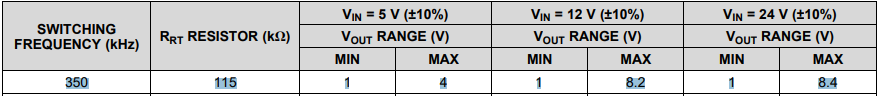
2.About Synchronization switching jitter

The synchronous frequency of 600 kHz was able to operate normally.
However, switching jitter is large.
Oscilloscope measurement result of Envelope mode was 30nsec.
Customers want to reduce to jitter.
Could you tell me how to improve jitter?

Best Regards,
Yusuke

  • Hi Yusuke-san,

    1. Can you provide a probe of the external sync frequency and SW node on the EVM before and after synchronization. I see that you are providing a 5V high/ 0V low which is following the datasheet recommendation. Is the duty cycle between 10% and 90%? I am guessing that you have the RT resistors set to 400kHz frequency and the external sync frequency set to 350kHz? For 24Vin/5Vout, switching from RT mode of 400kHz to SYNC mode of 350kHz should not have any issues.

    2. What is your load current? Depending on the load current, you may be in the transition phase between DCM and CCM which may be a bit jittery. You should not be seeing much jitter at around 1A and onwards.

    Regards,

    Jimmy

  • Hi Yusuke-san,

    Do you have any updates on this? The EVM should be able to externally sync with a function generator and switch between RT mode and SYNC mode seamlessly with minimal propagation delay.

    Regards,

    Jimmy

  • Jimmy-san ,

    Thank you for your kind support and message.
    I haven't received a response from them yet.

    By the way, have you confirmed this problem on EVM?

    I haven't got EVM.
    Therefore, I have not been able to confirm the phenomenon that has occurred in the customer.

    Best Regards,
    Yusuke
  • Yusuke-san,

    If the customer is having issues with external SYNC on the EVM, perhaps they didn't remove the J6 jumper. I took the EVM to the lab and tested for the following condition (VIN=24V, VOUT=5V; IOUT=4A; RT Mode = 600kHz; Sync Mode = 350kHz). You can see that after some delay the switch node changes from 600kHz to 350kHz. This confirms that the EVM can be externally synced to 350kHz for the condition mentioned above.

    LMZM33606_SYNC_E2E.pdf

    Regards,

    Jimmy

  • Jimmy-san,

    Thank you for your kind support.
    Customer again performed a synchronous operation test using EVM.

    Test condition is:
    Vin=24V、Vout=5V、"RT Mode = 600kHz → Sync Mode =400kHz"、Iout=No load

    LMZM33606 external synchronization operation was successful.

    However,There are cases with wide switching duty and narrow cases.
    A wide duty and a narrow duty are repeated alternately.

    Customer wants a fixed Duty behavior.
    (Duty changes may appear in the image as noise.)

    This phenomenon disappears when external synchronization is set to 420 kHz or higher or the input voltage is lowered.

    What is the cause of this phenomenon?

    LMZM33606 waveform.pdf

    Best Regards,
    Yusuke


  • Hi Yusuke-san,

    I will have the check this with an EVM in the lab. Let me gather some data and get back to you by tomorrow.

    Regards,
    Jimmy

  • Jimmy-san,

    Thank you for your response.
    I'm looking forward to hearing from you.

    Best Regards,
    Yusuke

  • Hi Yusuke-san,

    I took the LMZM33606EVM to the lab and tested for the following:

    • VIN = 24V ; VOUT = 5V; IOUT = No Load ; RT Mode = 600kHz ; External SYNC = 400kHz, 350kHz, 315kHz

    The EVM had J6 open and an external functional generator was connected to SYNC and GND. I did not see any intermittent pulse during the SYNC process. Attached is a zipped folder with the different test conditions: 2548.Orbison_24Vin_5Vout_SYNC_NoLoad.zip

    Only when I went below the recommended SYNC frequency of 350kHz did the power module have issues with proper SW operation. The SW node started oscillating around 320kHz and below. The waveform of 315kHz was captured to show the intermittent failure seen by the narrow pulses.

    From the waveform, CH 2 (SYNC) looks like it is roughly 1.25 divs which corresponds with 400kHz. Can you simply confirm this was the case from the customer?

    I will need to talk to the design engineer to discuss this discrepancy.

    Regards,

    Jimmy

  • Hi Yusuke-san,

    One simple modification to the EVM that I would suggest you test is removing the tantalum cap (C11). The combination of input, output, switching frequency and output capacitance may be resulting in an unstable switching operation. Removing the C11 will lower the output capacitance and remove some of the output ESR which will help with stability.

    Running the part at 350kHz with large output capacitance and 5V output may be a corner case condition that is causing the EVM to show signs of instability. At lower output voltages like 1.2 and 1.8V the tantalum capacitor may be more appropriate.

    Regards,

    Jimmy

  • Jimmy-san,

    Thank your for your strong support.
    About Synchronization operation
    The reason why the sync frequency did not match the setting was due to the SYNC voltage.
    As a result of changing the SYNC voltage to 3.3V, it worked normally.

    However, another problem has occurred.
    Could you check the attached file? 
    Let me ask another question.

    LMZM33603 LMZM33606.pdf

    Synchronous clock varies from 300kHz to 400kHz because of the trigger timing reset.
    Synchronization clock and the switching frequency are shifted.
    In the worst case, it takes 10 clock periods to synchronize.
    This problem is happening in both LMZM33606 and LMZM33603.

    Could you give me any advice on this cause and how to fix it?

    Best Regards,
    Yusuke


  • Jimmy-san,

    Thank your for your strong support.
    About Synchronization operation
    The reason why the sync frequency did not match the setting was due to the SYNC voltage.
    As a result of changing the SYNC voltage to 3.3V, it worked normally.

    However, another problem has occurred.
    Could you check the attached file? 
    Let me ask another question.

    1122.LMZM33603 LMZM33606.pdf

    Synchronous clock varies from 300kHz to 400kHz because of the trigger timing reset.
    Synchronization clock and the switching frequency are shifted.
    In the worst case, it takes 10 clock periods to synchronize.
    This problem is happening in both LMZM33606 and LMZM33603.

    Could you give me any advice on this cause and how to fix it?

    Best Regards,
    Yusuke


  • Jimmy-san,

    Thank you for your strong support.
    I'm looking forward to hearing from you.

    Best Regards,
    Yusuke

  • Yusuke-san,

    1. I'm not familiar with the trigger timing reset. Can you explain what that is and how you got CH 3 waveform? For my setup and waveforms that I've previously sent, my oscilloscope was always triggered off the rising edge of CH3 (SW node). 
    2. Did you get a chance to remove the polymer aluminum capacitor (C13) on the LMZM33606EVM and retest? Ideally you would want the external synchronization clock to be fixed at your desired switching frequency so that the device can be externally synchronized according to the clock.
    3. What would the waveform look like if you removed the C13 capacitor on LMZM33606EVM and have a minimum synchronization frequency of 350kHz?
    4. In that same waveform where you saw the shift in channel 2(SW) can you zoom out? I'd like to see how long the synchronization was successful and how long it took for the SW to pop out of synchronization.

    Regards,

    Jimmy

  • Jimmy-san,

    Thank you for your response and support.

    "I'm not familiar with the trigger timing reset. Can you explain what that is and how you got CH 3 waveform? For my setup and waveforms that I've previously sent, my oscilloscope was always triggered off the rising edge of CH3 (SW node). "

    →I apologize my explanation is insufficient.
     “Trigger timing reset” is a function on the customer application.
      Depending on the application specifications, the clock frequency may change momentarily.
      If the sync clock goes back and forth between 300kHz and 400kHz, the reported problem will occur.
      If the clock fluctuates, will there be a loss of synchronization as sent?
      Please advise about the speed of LMZM following clock fluctuations?

    "Did you get a chance to remove the polymer aluminum capacitor (C13) on the LMZM33606EVM and retest? Ideally you would want the external synchronization clock to be fixed at your desired switching frequency so that the device can be externally synchronized according to the clock.
    What would the waveform look like if you removed the C13 capacitor on LMZM33606EVM and have a minimum synchronization frequency of 350kHz?"

    →I will try that.

    ”In that same waveform where you saw the shift in channel 2(SW) can you zoom out? I'd like to see how long the synchronization was successful and how long it took for the SW to pop out of synchronization.”

    →I will contact the customer with the waveform acquisition request.

    Best Regards,
    Yusuke

  • Hi Yusuke-san,

    Please contact me offline at j-hua@ti.com to get more frequent updates on this troubleshooting. I will have to look to see if fluctuation in external sync frequency might cause issues with the device synchronization feature. One thing I would like to add is that when you change the external synchronization on the fly I would expect the internal PLL circuitry to have some delay and react to the new switching frequency. This may be the reason you are seeing this "10 clock periods to synchronize". Can you provide time period measurements(cycle by cycle) of when the CH2 is syncing to CH1 and when CH2 is not syncing to CH1? From the pdf image you've attached, the time scale division is not clear. 

    Also please provide some updates on the customer's testing so I can understand if my suggestion helped in any form. I will be closing this thread and waiting to hear back from you.

    Regards,

    Jimmy