This thread has been locked.
If you have a related question, please click the "Ask a related question" button in the top right corner. The newly created question will be automatically linked to this question.
Tool/software: Code Composer Studio
Hi,
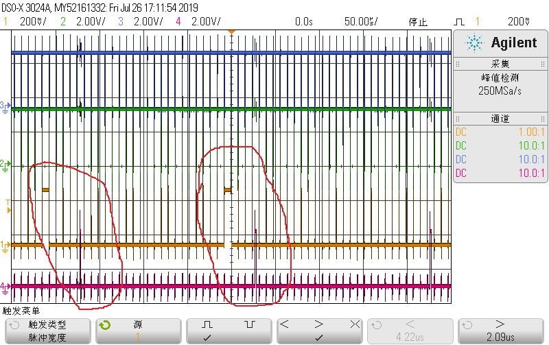
My custom has a problem in UCD3138 Bulk-Boost application:DPWM loses two periods which change into one period when in UCD3138 DPWM TRIANGULAR Mode.
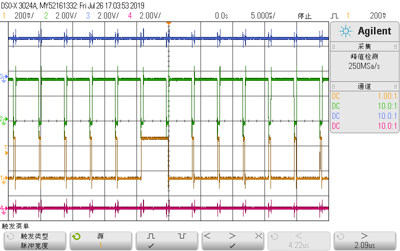
DPWM2B basic configuration:
TRIANGULAR Mode (PWM_MODE = 3)
Output 1-D (D_ENABLE =1)
Invertion(PWM_B_INV = 1)
Synchronization(MSYNC_SLAVE_EN = 1)
GLOBAL_PERIOD_EN = 1
CLA_EN = 1
Turn on or off AMS (Auto Mode Swtiching) makes no effect on this phenomenon.
After tests on all kinds of registers,it shows that the value of CycleAdjustA and CycleAdjustB is correlative with losing edge phenomenon.The configuration is as follows:
Triangle mode.
Value of CycleAdjustA and CycleAdjustB should be equal with or geater than 280(70ns)
There is no relationship with min and max duty.
There is no relationship with running frequency.
According to the UCD3138_TRM(High resolution is 250 picosec, and the range of a signed 16 bit value is ±2e15.), these 2 registers can be >0 or <0, but as my experimentation if every one or both of them are set to a value <280, occasionally 2 edges can be lost.
So can someone confirm the reason and the accurate value of the min limits of these 2 registers,or anything that have been ignored.
Your reply is highly appciated.
what's your topology? why you use TRIANGULAR Mode?
these two configurations give same result as use D without inverting, why you use these configuration?
Output 1-D (D_ENABLE =1)
Invertion(PWM_B_INV = 1)
Hi
Topology: Bidirection Bulk-Boost Module Power Supply
Because of bidirection design, I think use triangular mode is more stable than others.
These two configurations make DPWM2B waves' phase shift 180° than DPWM1A
Now I change DPWM period and duty cycle without shut down it on the condition that the value of CycleAdjustA is more than 500,it won't appear the Phenomenon that two periods changing into one.
I still wonder why the period-losing phenomenon disappear when the value of CycleAdjustA is more than 280,like what I write in the question.
Without detailed dead time and cycle adjust information, it's hard to tell what's going on, and we have certainly never tried your exact configuration.
Normally to get 180 degrees out of phase we use the phase trigger mechanism.
Typically when you get a shoot through like that, it is because an active edge has moved in or out of the update window. Normally we recommend setting the bit which makes the DPWM update at the end of the period - EVENT_UP_SEL. In fact, it is set by default. this means that you will have a time slot at the beginning of the DPWM period where all the events are calculated and updated. If an edge moves in or out of this slot, you may have pulse extension. Of course, since you say that the DPWM2B will be 180 degrees out of phase, and it is triangular mode, then the edges on short pulses will be right there at the period end.
That would be my primary candidate. If it was me, and I wanted 180 degrees out of phase, I would try the phase trigger instead. Triangular modulation is great at keeping things away from the end of the period.
Hi Lan,
I am the original user who raise this question.
I appreciate you for your help! Your suggestions are absolutely helpful!
Here are some results I get after some new experiments.
1. If EVENT_UP_SEL=1, edges loss cannot be avoid, even the duty cycle is greater than 7%, for some disturbance added to the duty cycle by the Filter, I guess. The minimum duty cycle cannot fit my application. So, this DPWM update window mode is not usable for my project.
2. I failed to use the the phase trigger mechanism, by which, I can configue the DPWM as normal mode(not inversed, duty=D). The phase trigger doesn't work, I don't know what conditions are suitable for this mechanism, maybe it is inactive in triangular mode. With my project, DPWM0 is the master, and others are synchronized with it as slaves, for DPWM(0-3) should keep strict phase relationship. I DPWM(1-3) are not synchronized with DPWM0, it seems that fixed phase relationship cannot get.
3. When EVENT_UP_SEL=0, edges loss is conquered, but as a side effect, the interrupts of AMS(Automatic Mode Switch) cannot be generated. Why? I now use other mechanism but AMS interrupts for mode switching. In Bulk-Boost Module, mode switching is needed.
I hope to know more about the internal work principle of DPWMs, and more, something about the FILTER, FE, etc.
Thank you!
Of course the phase trigger works with triangular mode. If you look at the EVM code for the PFC for the Interleaved version, you'll see an example of how to do it.
As a general rule, if something isn't working as you expect on the UCD, but it works in an EVM code, you need to study the EVM code carefully to find out which bits you are setting wrong.
As far as learning more about the DPWMs, FIlter, and FE, I strongly suggest reading carefully through the UCD3138 Technical Reference Manual. I have worked with a few other people to put lots of useful information in there. And the the second suggestion is to always, if at all possible, start with an existing EVM code, and migrate to what you need.
The recommendation to your issue is still the same - use the phase trigger to put the two signals 180 degrees out of phase, and then you can go up to a relatively high duty cycle without having any collisions with the update window.
Hi,
I have read the code of EVM of PFC, and test kinds of configutation combinations on UCD3138A.
Under the following condition: for DPWM(0-3), D_ENABLE=0, mode=TRIANGULAR, DPWM0.MSYNC_SLAVE_EN=0, DPWM(0-3).MSYNC_SLAVE_EN=1,
I write a number to DPWMPHASETRIG of DPWM0, the phase of DPWM0 changed, the phase defference between DPWM(1-3) is 0, write any number to that of DPWM(1-3), there is no effect, the phase defference between DPWM(1-3) is always 0.
If I set the DPWM(0-3).MSYNC_SLAVE_EN=0, and then write a number to DPWMPHASETRIG of DPWM(1-3), I cannot get a fixed phase difference between DPWM(1-3) and DPWM0, it seems that I cannot control the phase of DPWM(1-3) by these configurations. And more, if all DPWMs are set to master, they cannot be sychronized.
I am confused that if the DPWMPHASETRIG works under any condition.
So, by now, there is the only method for me to get 180 degrees phase, that is: set the slave DPWMs by: D_ENABLE=1, PWM_B_INV=1.
As for the other question, I now set EVENT_UP_SEL=0, all signals works fine, that means "update right away". what does this exactly mean? When dose the period data are exactly been updated? If the duty cycle is near to 0, can its edge enter the update window?
Thank you!
You need to set the desired phase delay on the phasetrigger for the master. You need to set the msync slave enable on the slave.
When you say the phase of 0 changes and 1-3 stays the same, that's because you are changing the delay to i-3 1-3 are all being controlled by 0, because that is how they are set in the DPWMMUX register in loop mux. If you want to differentiate all the DPWMs, then you need to string things
For instance on our PSFB, I think we make DPWM0 the master, with 1/2 period in the phase trigger. DPWM1 is slaved to DPWM0. Then we put a half period into the phase trigger for DPWM1, and slave DPWM2 to it. This means that DPWM2 is synchronized with DPWM0, since the total delay equals one period. Then we can slave DPWM3 to DPWM0 as well, and it will be synchronized to DPWM2.. So when you think you're shifting DPWM0, you're actually shifting DPWMs 1-3. Their start occurs at the start of DPWM0 + the DPWM0 phase trigger value.
I now understand that a DPWM is synchronized to its precursor but the master.
For instance, I want DPWM0,1 are the same phase, and DPWM2,3 are the same phase and shift 180 degrees to DPWM0,1, I can use the following codes:
Dpwm0Regs.DPWMCTRL0.bit.MSYNC_SLAVE_EN = 0;//the only mster
Dpwm1Regs.DPWMCTRL0.bit.MSYNC_SLAVE_EN = 1;//slave
Dpwm2Regs.DPWMCTRL0.bit.MSYNC_SLAVE_EN = 1;//slave
Dpwm3Regs.DPWMCTRL0.bit.MSYNC_SLAVE_EN = 1;//slave
LoopMuxRegs.DPWMMUX.bit.DPWM1_SYNC_SEL = 0;//synchronized to DPWM0
LoopMuxRegs.DPWMMUX.bit.DPWM2_SYNC_SEL = 1;//synchronized to DPWM1
LoopMuxRegs.DPWMMUX.bit.DPWM3_SYNC_SEL = 2;//synchronized to DPWM2
Dpwm0Regs.DPWMPHASETRIG.all = 0;//phase between 0 and 1 is 0
Dpwm1Regs.DPWMPHASETRIG.all = period >> 1;//phase between 1 and 2 is 180 degrees
Dpwm2Regs.DPWMPHASETRIG.all = 0;//phase between 2 and 3 is 0
Thank you for the help!
Could you tell me more secrets about the "update window"? :-)
I can tell you to look at the various migrations guides and programmer's manuals for each chip to see what the update window is for each chip. It's gotten longer as we have added features with the later devices and the A devices. Note that there are special requirements when doing the LLC on non-A parts for sample trigger, and the need to have the sampling synchronous with the switching frequency. These requirements are gone on the A parts.
Other than that, I'm going to say this issue is resolved. If you want to learn more about the update window, look at the Technical Reference Manual and the EVM codes,and see how they're done.