This thread has been locked.

If you have a related question, please click the "Ask a related question" button in the top right corner. The newly created question will be automatically linked to this question.

UCC28950: Shoot through in PMP8740

Part Number: UCC28950
Other Parts Discussed in Thread: PMP8740

Hi,

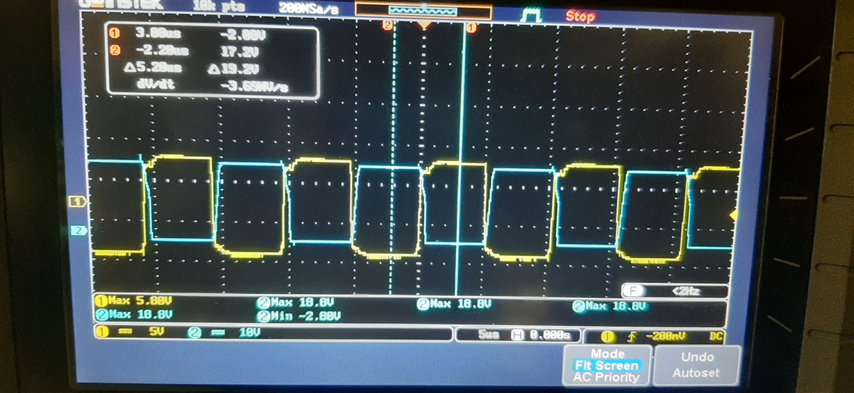
I have modified PMP8740 schematic a little according to my use. But the thing is that when I am trying to turn on DC-DC converter with 200V DC minor shoot through is happening because of the position change of gate driver mostly.

It is happening due to delayed turn off of the high side switch. and which is severe in Q8- Q15 half-bridge tan the other. 

But I think I can avoid this condition by adding some more delay to the dead band between A, B MOSFETs, and C, D MOSFETs.

How can I increase the dead time?

I read that by changing the resistor of DELAB and DELCD. But it is specified that this resistor should be in the range of 10k and 20k. Since in the design it is using 49.9k. So got confused...

So what I have to do to make a dead time about 10-20% of the time period?

  • Hello Nidheesh

    The allowed range for the resistors at the DELAB, DELCD and DELEF pins is 13k to 91k so the 49.9k value is allowed. You can increase the AB and CD delays increasing the resistor value. The total resistance of the potential divider at the ADEL and ADELEF pins should be in the range from 10k to 20k so this may be where you were getting the values.

    Please note that the DELAB, DELCD and DELEF pins set a baseline delay that is modified according to the signal at the ADEL and ADELEF pins.

    Regards

    Colin

  • Hi Colin,

    So if I am increasing the resistance of Rab and Rcd , I can increase delay right?

    So is this setting the minimum delay?

    Because at any circumstances I don't want to decrease the delay below the set value.

    Regards

    Nidheesh

  • Hi Nidheesh

    Increasing Rab and Rcd will increase the 'baseline' delay.

    The potential divider at the ADEL pin sets the KA parameter and modifies the baseline delay (KA=0) according to the curves in Fig 29 and Fig 30 of the datasheet (for Rab or Rcd = 13k and 90k). This can be useful sometimes because the optimum primary side delays reduce as primary currents increase.

    Ref sets the baseline SR turn-off delay Figure 31 Fig 32 and Fig 33. Increasing the resistance, increases the baseline delay.

    The potential divider at the ADELEF pin sets the KA parameter and modifies the baseline delay (KA=0) according to the curves in Fig 32 and Fig 33 of the datasheet (for Ref = 13k and 90k). This can be useful because the optimum secondary side delay INCREASES as primary currents increase.


    Regards
    Colin