A related question is a question created from another question. When the related question is created, it will be automatically linked to the original question.
If you have a related question, please click the "Ask a related question" button in the top right corner. The newly created question will be automatically linked to this question.
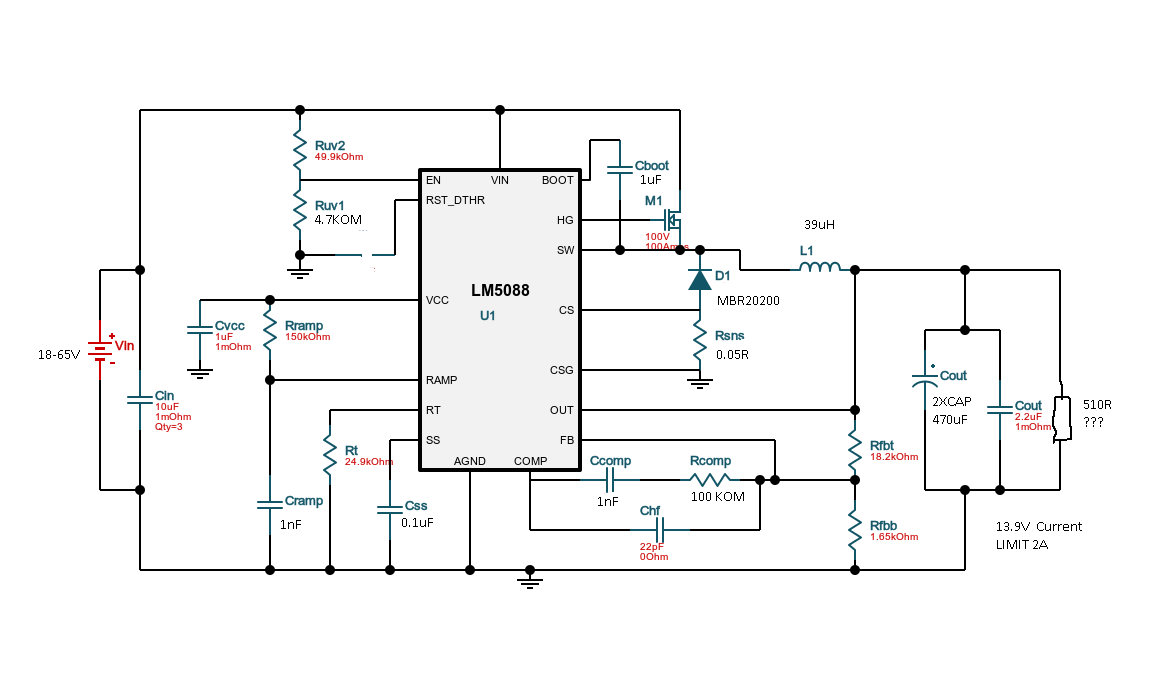
Good evening. Finally they sent me the circuit boards. I collected everything. Everything is working. One problem. The circuit does not work without connecting an external load. That is, if the output hangs in the air, then the output voltage is floating in the range from 7-11 volts. I achieved more or less good results by preloading the circuit with a 510 ohm resistor. But I make an uninterruptible power supply and my own current consumption is of great importance to me. Is it possible to count something in the circuit in order to achieve an increase in the resistance of the resistor at the output. And one more incomprehensible thing. When I load an output, for example, with a resistor of 1 kilo-ohm, I observe the following picture - When the input voltage is from 17 to 20 volts, the output is sawtooth, when the voltage at the input is from 21 to 23, the output is 13.9 volts. At a voltage of 24 to 26 volts, again a sawtooth signal, over 26 volts at the output, again a normal signal of 13.9 volts. Is it really possible to do without a load resistor at the output, or it can somehow increase its resistance, but so that with the entire operating range from 18-65 volts there is no saw signal. I forgot to say that the LM5088-MH2 microcircuit came to me, so I shorted the RES output so that the microcircuit did not go into a constant reboot, but worked as a current limiter. With this, everything is in order, in the entire operating range, the output current does not exceed 2,3 amperes
I also forgot to say that if the circuit is loaded with a resistor or other load with a resistance of less than 510 ohms, then the circuit works perfectly in the entire range of input voltages. In the diagram, I changed the ratings of some elements, since the circuit proposed by the designer worked even less stable. The bootstrap capacitor had to be increased from 0.1uF to 1 uF, as well as changing the ratings in the ramp inclination circuit. But the manipulations with the components still did not bring the desired result, if you do not load the circuit with a current of at least 20 mA, then a saw appears at certain output voltage ranges
A regulator should maintain its output voltage with or without load. Considering you are interested in maintaining high efficiency, loading with RFBT should not be a solution to consider, rather finding the root cause of the issue should be.
I will work in analyzing the design and get back to you shortly with a solution.
at idle, the output voltage of 13.8 volts is stabilized provided that the input voltage is at least 30 volts. If you load the output with a 510 ohm resistor, then the input voltage level may already be from 18 volts. If you even more heavily load the output with a resistance of less than 510 ohms, then the circuit starts to work normally already from 15-16 volts. In general, the higher the load, the better the circuit. But I would like my converter to consume as little current as possible
I recommend using the quickstart calculator (downloadable from the product folder) to verify component values, particularly for compensation. The boot cap should be 0.1uF, about 1/10 of the VCC cap. Also, a 100V Schottky diode is sufficient for this input. You might also check the MOSFET and make sure the Rdson is rated for a Vgs of 4.5V.
Good morning. I am using the IRF3710 transistor. With this transistor, if you put the bootstrap capacitor below 0.68 microfarads, then a stable start of the circuit turns out to be about 22-24 volts, and I need 18. I suspect that the gate capacitance of the selected transistor is too high
The transistor I selected has an input capacitance 2 times higher than what your designer offers. Since changing the correction circuits did not lead to proper results, I suspect that it is a matter of choosing a transistor. Please, look, is it suitable for my irf3710 circuit?
Correct, this FET is too capacitive. Its gate charge Qg at Vgs = 10V is 130nC. This leads to high gate drive power loss (gate drive loss is Qg*Vgs*Fsw). Related to this, the current that's requires from the LM5088's internal VCC regulator may be excessive (it's only rated for 30mA).
Ty using a lower capacitance FET, for example CSD19534Q5A 100V NexFET from TI. This has an SON 5 x 6mm footprint and is ideal for a 2A load current.