This thread has been locked.

If you have a related question, please click the "Ask a related question" button in the top right corner. The newly created question will be automatically linked to this question.

TPS3701 Wired-Or configuration for bipolar power supply

Other Parts Discussed in Thread: TPS7A39, TPS3701

Hello. 

According to my previous thread I've got one question - about this schematic.

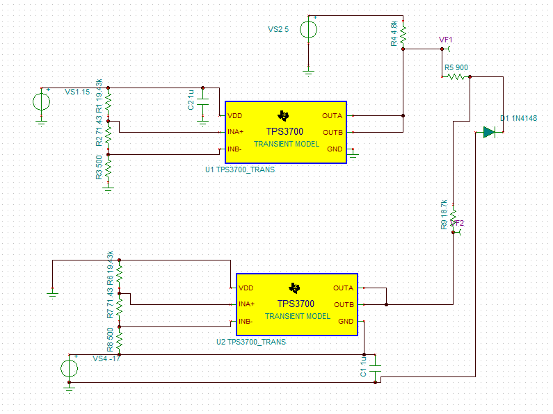
If I'm going to use only one EN signal to feed a few LDO's then I should pick VF1 output or those two (VF1 and VF2) should be combined via some logic?
My regulators are one pair of TPS7A3301 with TPS7A4701 and TPS7A39 - pull up voltage will be 6V just because I want TPS7A3301 to be enabled with the same time.

Have nice day, thank you.

  • Hi Mateusz

    You have to use VF1 as output. 

    It will vary as following table -

    Case

    +ve supply

    -ve supply

    Output(mV)

    1

    Out of window

    In the window

    10-15

    2

    Out of window

    Out of window

    10-15

    3

    In the window

    Out of window

    320

    4

    In the window

    In the window

    5 Volt

    5

    Out of window

    In the window

    10-15

    Regards

    Trailokya

  • Just quick question.
    How to calculate R4, R5 and R9 for 6V pull-up voltage?

    Let's assume that I will use 50K pull-up resistor (but I could use basically every value that will be better).

    D1 will be 1N4148 

  • Hi Mateusz

    Calculation of R4 = RPUA,R5 = RPUB, R9 = RPUC can be studied under 4 cases -

    Case 1- When Reset is not asserted for both +ve and -ve supply

    Output will be pulled up to VOH level. Output terminal of both +ve and –ve supply monitor will see VOH voltage (≈ VPU). In case of –ve supply monitor GND will be at –ve potential. The recommended operating max for OUTA and OUTB pin with respect to GND is 18V for TP3700.

    So 18 ≥ VPU + Max {VTHP , VTHN}…………..(iv)

    Case 2- When Reset is asserted for -ve supply

    Output of –ve supply will go to Vol level with respect to GND. The diode will turn on. Hence current in Output terminal of –ve power supply (which is at VOL) will be

    IOL =

    VFB = Forward bias of the diode

    VSS = -ve supply

    IOL max should not be more than 10mA. That imposes the minimum limit on RPUC resistor. Let’s assume the diode is not present then potential at point D should be less than –VFB volt in case of VSSmin for negative supply monitor when RESET for UV is asserted. This impose max limitation on RPUC for a given RPUA and RPUB.

    RPUA and RPUB are generally kept high (in the range of 10k to 50k). RPUA and RPUB should be selected in a ration such as

    100mV ≤ Vout ≤ VOL for this case.


    Case 3- When Reset is asserted for +ve supply

    Output will be pulled low by output pin of +ve supply monitor. -Ve supply monitor out pin will be in High Z condition so there will be no current (or leakage current 300nA max) in RPUB and RPUC. The diode will be off in this case.


    Case 4- When Reset is asserted on both +ve and -ve supply

    Output will be pulled low by output pin of +ve supply monitor. –Ve supply monitor outpin will be at –VSS level. The diode will turn on and supply IOL to –ve voltage monitor out pin.

    Regards

    Trailokya

  • Hello again.

    I made this circuit proposed by you, but I've still got some issues to calculate R4, R5, R9.

    At this moment my design is partially working - when VCC (17V in my case) is out of the window then everything is ok.
    But when VEE is out of the window (-17V) there is something went wrong :(

    My VPU is 6V in this case, I've got 1N4148 diode, but I could replace it with SK13 or similiar.
    I used an excel sheet to calculate proper values of resistors and those are fine.

    My UV is set to +/-16V and OV is set to +/-18V.
    VCC and VEE are +/-17V.

    Would you be so kindly to help me out?
    Maybe some example that I could use it in future to calculate those resistors, sorry but your previous post is kinda difficult to me to understand.

  • Hi Mateusz

    As per my understanding, your setup is as follow -

    VPU = 6V

    Window -16V to -18V for -ve supply and 16V to 18V for +ve supply. 

    In this case when you are in the window for -ve rail, the diode is ON and circuit should be working fine. But when you are going out of window , let say VEE = -15V 

    in that case output terminal of -Ve rail monitoring supervisor will see 6 - (-15) = 21V. Which is more than ABS max of the out pin . If you want to monitor 17V supply , I would recommend to use TPS3701. That has higher Voltage rating for all pins. 

    Regards

    Trailokya

  • Hi again.
    I'm already using TPS3701 in my design ;)

    I was aware of this limitation.
    What you mentioned above is exacly my case and I've got some issues with picking proper resistors to make it working fine in every possible case.
    At this moment only VCC monitoring is working as it supose too.

    VEE is kinda broken partially.

  • Hi 

    For 6V pullup please use  R4 = 57K ,R5 = 10k ,R9 = 10k . It will work for both the cases.

    Regards

    Trailokya