This thread has been locked.

If you have a related question, please click the "Ask a related question" button in the top right corner. The newly created question will be automatically linked to this question.

BQ24610: ACFET Not turning on

Part Number: BQ24610

Hi, Attached is the pdf of simple charger in which with or without battery connected, ACFET is never turning on.

VREF is 3.3V, ACDRV is SMPS voltage - 0.4(Approximate).

Acset = 0.8V

Iset2 = 0.3V

Iset1 = 0.79V

VR4 = VR18 = 0V(No load connected)

HIDRV = 5V

LODRV = 0V

Led Status : D1 and D3 is glowing.

SMPS voltage tried in range of 5V to 19V

Also when input smps is not connected and when running on battery, BATFET is turning on (BATDRV = Vbat - 5V(Approximate))

Can any one help me out?VVC_SCH_REVE_23AUG2019.pdf

Thank you 

  • Hi Kishan,

        Is D2 off when SMPS is on? STAT1 on and STAT2 off indicates charge in progress. Instead of DC values it will be good to look at scope captures of HIDRV and LODRV. HIDRV should be at PH + REGN when on, and LODRV should be at REGN voltage when on. For ACDRV on, you should measure VCC - REGN for negative VGS to turn on the input reverse blocking PFETs. ACDRV and BATDRV are asynchronous and switch between each other in the event that input voltage is lost or charger enters SLEEP mode.

    Please perform 2 tests:

    1. Scope capture of VCC, SRN, ACDRV, BATDRV
    2. HIDRV, LODRV, BTST, and PH when STAT1 on and STAT2 off (when charge is in progress and charger should be switching)
  • Hello Kedar,

    Thank you for reply and support. 

    All the DC values are taken from scope + multimeter. Attached are the images of VCC, SRN, ACDRV,BATDRV, HIDRV, LODRV, BTST and PH of two different boards(BRD1 and BRD2).

    While capturing waveform, both boards have STAT1 LED on and STAT2 LED off and PG is on.

    And also battery is not connected in both boards, Only input is connected which is not getting in the output. Also instead of 103AT thermistor, a 10K resistor is connected to therm input.

    Regards

    KishanIMG.zip

  • Hi,

    In addition to these, 

    I tried shorting ACFET drain and source. In that case battery is starting to charging, but when battery is connected and smps is turned on, then BATDRV is not going low and high currrent is flowing from input to battery through BATDRV.

    When battery is connected after turning on SMPS, then there is no issue of overcurent.

    Regards

    Kishan

  • Hello,

    While charging also, its always charging in 120mA. 

    Regards

    Kishan

  • Hi Kishan,

      Is this on a custom board or the BQ24610EVM? These values do not look right at all and charger is not switching at all in this case. Based on your system here is what values you should be expecting:

    VCC = 15V

    REGN = 6V

    ACDRV = VCC - REGN = 9V (when input is valid source VCC>VUVLO, VCC>SRN + SLEEP threshold)

    BATDRV = VCC (when input is valid source BATDRV should be pulled up to VCC and BATFET will be off. This value would be reversed with ACDRV if there is no valid input source)

    PH = switch between VCC and GND at 600kHz

    LODRV = switch between GND and REGN

    HIDRV = switch between GND and PH + REGN

  • Hello Kedar,

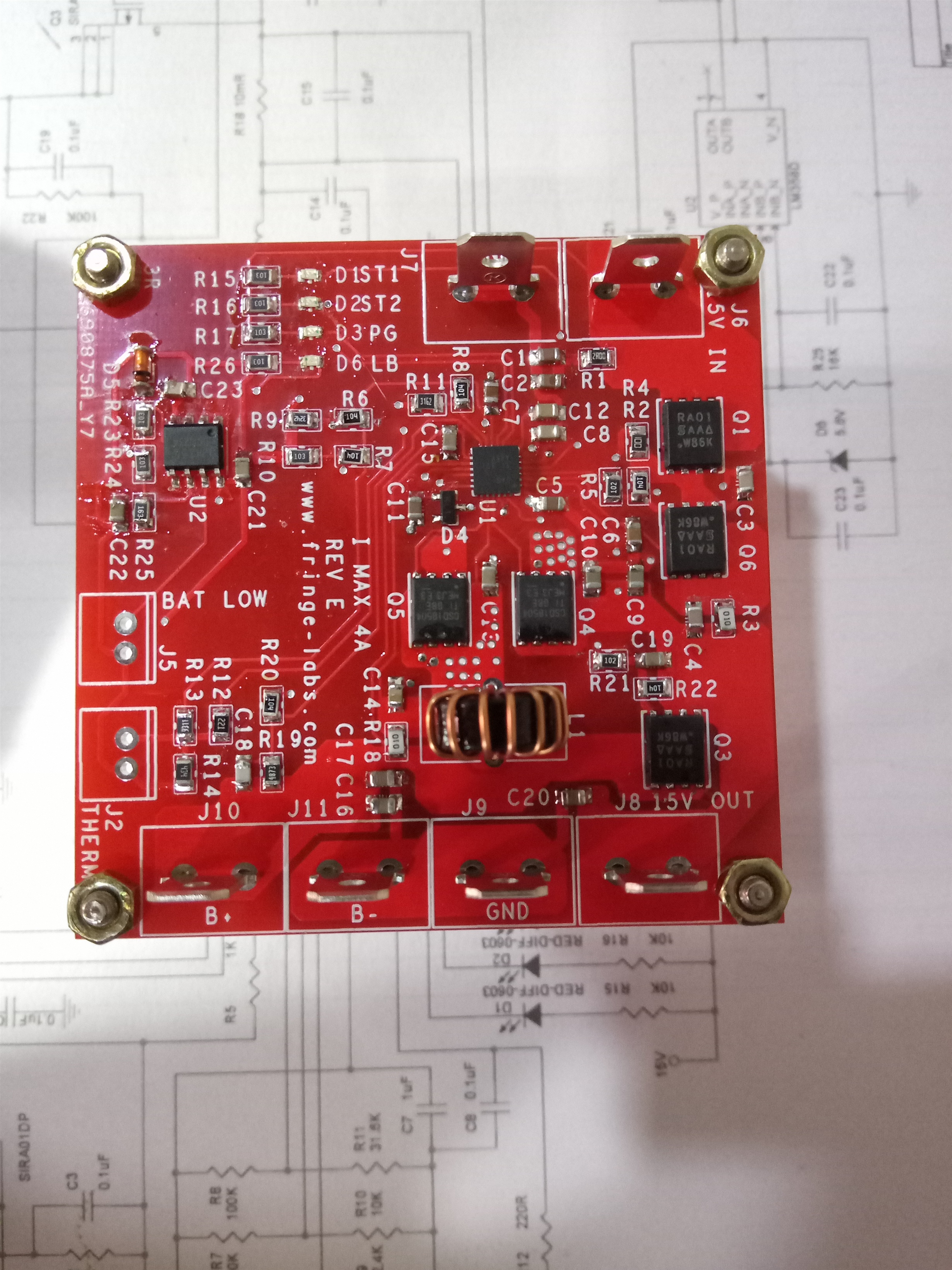
    This one is a custom board and attached is the top and bottom pdf and one image of board

    Sorry for trouble on ACFET, It is now solved and was due to a cut in pcb trace(may be happened while shipment). After that i checked all connections.

    But now still battery charging have some issue, Attached is the waveform of BTST, PH, HDRV, LDRV and REGN. Issue is output current is not getting controlled. My inductor is 10uH and when using this, charging current is 120mA when device is turned on. After that i reduced to 6.8uH which is giving around 250mA and again reducing to 2.7uH, output is around 1A.

    But in the case of 2.7uH also precharge is not happening and duty cycle seems to be constant on all case like in attached image. Is precharge supposed to happen on all turn on of input smps? What will be cause of above problem?

    (Inductance series resistance is very low and also tried ferrite drum core which having higher radius and output is same)

    (Battery voltage is around 11V and SMPS is 15V, Efficiency is too low, Input and output current are almost same)

    BRD3.zip

    2475.TOP.pdf

    2475.TOP.pdf

  • Hello,

    Bottom layer.

    7356.BOT.pdf

    Regards

    Kishan

  • Hi Kishan,

       Reviewing the layout will take some time. I will get back to you on 9/30 with comments. I will also update with results from EVM so you can see how results should look like. When changing inductor values, make sure the LC output resonant frequency is within the specified range shown in the datasheet. Also SMPS voltage is 15V, but what is actual voltage measured at SRN and VCC close to the IC?

  • Hello Kedar,

    Thanks a lot for your  support.

    Attached is the gerber for the board.

    Also VCC measured close to IC decap is equal to SMPS voltage and SRN voltage on C15(which is close to IC) is equal to battery voltage.

    By trying many values of inductor, below 2.2uH the device is giving very low current(sometimes average current shoots to 1.5 A when SMPS voltage is changed). At 2.2uH output current is stable but only 1A max and duty is constant at 80% as in previous images. Increasing to 10uH, the current is decreasing proportional to the inductance value.

    Regards

    Kishan

    VVC_GRB_REVE_26AUG2019.zip

  • Hi Kishan,

       I apologize for the delay. I am still looking into this issue.

  • Hi Kishan,

        Ideally you should be observing PH switching between your input voltage and slightly below ground. HIDRV should be switching between PH + REGN and ground (so 15V + 6V). For fluctuating charge current please refer to datasheet section 10.2.2.1 Inductor selection. This details how to choose the inductor based off of desired ripple current, and how much saturation current the inductor should be capable of. LC filter should be selected in the resonant frequency range, but smaller inductance will have higher ripple current (faster response to slew rate changes) and larger inductors would have higher DCR effecting efficiency more. Keep LC resonant frequency between 12kHz and 17kHz.

       Precharge current should only be based off of battery voltage. I would highly recommend ordering an EVM and basing design off of that.