This thread has been locked.

If you have a related question, please click the "Ask a related question" button in the top right corner. The newly created question will be automatically linked to this question.

LM5160-Q1: LM5160-Q1 Questions

Part Number: LM5160-Q1

LM5160-Q1 Isolated DC/DC:

Input : 6V~60V

Out put: 15V /500mA

Trans: 1:3

SCH as below:

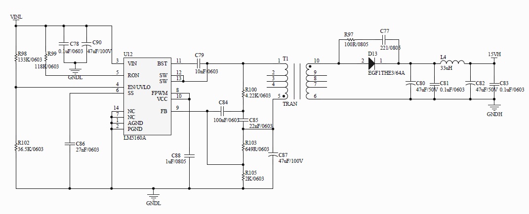
Q1:  NO load, output normal is DC15V . When loading >100mA, Output abnormal is 0V. SCH   SCH is correct or not? If have some design referrence messages? Can other solutions be recommended?

Q2:  What is the max current of LM5160-Q1 @ DC15V(Input 6~60V)?

  • Hello,

    a 1:3 turns ratio is not advised for FlyBuck topology.  Recommend an inverting Buck boost on the primary, setting Vout primary to -15V out and use a 1:1 turns ratio to get 15V out at 0.5A.  With a 6V input voltage, you should be able to obtain 0.5A out.  Please see attached spreadsheet for basic design approach.  Please refer to the "Designs" tab for the inputs matching your requirements and refer to the "Fly-buck-boost" tab for the design approach.  

    IBB FlyBuck Calculator_Rev1p03.xlsx

    Hope this helps?

  • Dear David,

    Thanks for your great supports~

    IBB FlyBuck Calculator_Rev1p03, this message is very useful~

    another question:

    Q1: For your suggestion, Setting Vout primary to -15V out  use a 1:1 turns ratio .

         but Vout=17V at no load,

         if load setting to 10mA, Vout=15V.

         if load setting to 200mA, Vout= 13.5V only ,

          if load >300mA, Vout  will be lower.

          Vout 15V can't output stably . Whether have some better ways to make output more stable?

    Q2: Compensation setting as below, RFB(bottom) calculated is 3.077KΩ, why selected is 5.714 KΩ? 

           If selected other value? RFB(top) =133K and RFB(bot)=20KΩ.

    Q3: Ripple injection compensation: Cac ,Cr ,Rr  ,Is there a detailed calculation formula? How to understand worst case ripple 50mV?

    I hope to receive your reply. Thank you.~

  • Hello,

    I am assuming the feedback regarding load regulation is with a 1:1 transformer in a buck boost configuration?

    Answer 1.

    Re: the output rising at no load.  The output of the secondary will always need a few mA's of current to keep it from rising, an alternative to a pre load resistor is to use a Zener to clamp rather than continually pulling current.

    Re: the Output dropping at 200mA, you will need to make sure the leakage inductance of the transformer is small, suggest <1% of Lprimary.

    Answer 2.

    Set the feedback resistors to the values you mentioned above.  This is OK.

    Answer 3. 

    Set Cr and Rr at Vin min, this is worse case as per Equation 8 in the datasheet.  You can reduce the worse case ripple voltage to 25mV.

    Hope this helps?

  • Dear David,

          Thanks,  About answer 3 , I still don't quite understand.

           I plan to design Cr=1nF , Rr=47KΩ, Cac=0.1uF, This setting may meet reference value,Is this OK? 

           I try to debug and setting Cr=22nF , Rr=4.7KΩ, Cac=0.1uF ,Vout has no difference. Are there relevant waveform for reference(Cac both end)?

           RFB1 add C1, VFB waveform get better ,whether may setting as this?

     Kind Regards

    Aihua

  • Hi Aihua,

    If you follow the procedure posted above for setting the ripple voltage at Vin, you should have adequate ripple at the Feedback node.  this can be confirmed by measuring the Ripple voltage on the feedback node, which is Feedback side of Cac.

    If you find that adding C1 across the bottom feedback resistor helps this indicates you have a noise/layout issue.  But I would make sure the design is right by following the recommendations in my answers above.  

    For the layout recommendations, please follow closely the advice given in the Datasheet as well as the layout in the EVM particularly with respects to the components around the device.  Again, I do not expect things to work well if you are using a 1:3 turns ratio, this not not recommended irrespective of the layout being ideal...

    Hope this helps?

  • Dear David,

           Turns ratio will set to 1:1 or 1:2, Do you suggest which way? I have designed and prepare to debug these two ways.

           If there are some questions, I would like to ask you again.Thanks for your great supports~

     Kind Regards

    Aihua

  • Hello Aihua,

    You can try both ways, I would advise the 1:1 in fly buck boost as more favorable for better load regulation.  see feedback in post above.

    Hope this helps?

  • Dear David,

           Thanks, Understand.

    Kind Regards,

    Aihua

  • Thanks Aihua,

    I will close this thread for now.  If anything else comes up, please feel free to reopen.

    Thanks

  • Dear David,

           OK, Thanks a lot~

    Kind Regards,

    Aihua

  • Dear David,

          Hi,I'm sorry to trouble you again. I want to ask new question about COT setting.

          Q1: Ripple injection on FB Range: Wether it is 25mV ~50mV?  The max value?

          Q2:Aaccording to Reference setting,Vout value range is 16.5V~13.5V @ 0~200mA .

                But according to figure as below,Vout value range is very good,15.1V~14.8V @0~200mA. That Setting is not COT.

                Wether has any questions? Do you have any suggest?


     Kind Regards

     Aihua

  • Hello Aihua,

    The ripple injection voltage ideally should be set between 25 and 50mV.

    As mentioned previously, I do not recommend the configuration you show in the figure posted.  Please follow the traditional configuration of Rr, Cr and Cac.  Details of how to design with these values are given in the datasheet.  If you have any further questions about designing Type III configuration please feel free to open new thread and discuss.

    Thanks.

    David.

  • Dear  David,

         Thanks for your great supports~

         I will try to debug as your suggest. If have some questions,I will open new thread. Thanks~

    Best Regards

    Aihua