This thread has been locked.

If you have a related question, please click the "Ask a related question" button in the top right corner. The newly created question will be automatically linked to this question.

TPS55340: DAC Controlled Boost converter output

Part Number: TPS55340

hi,

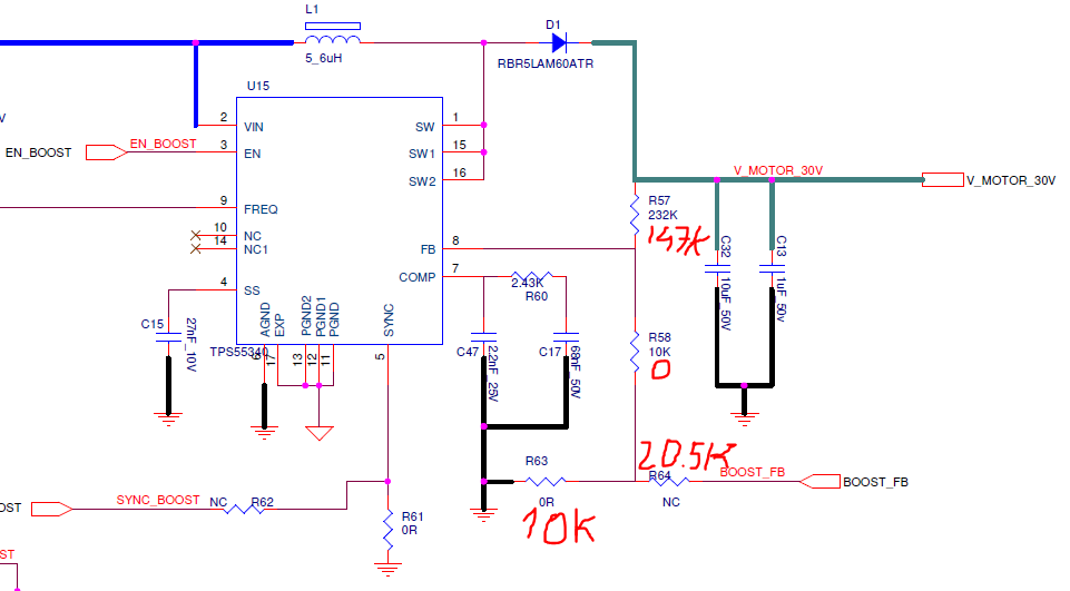
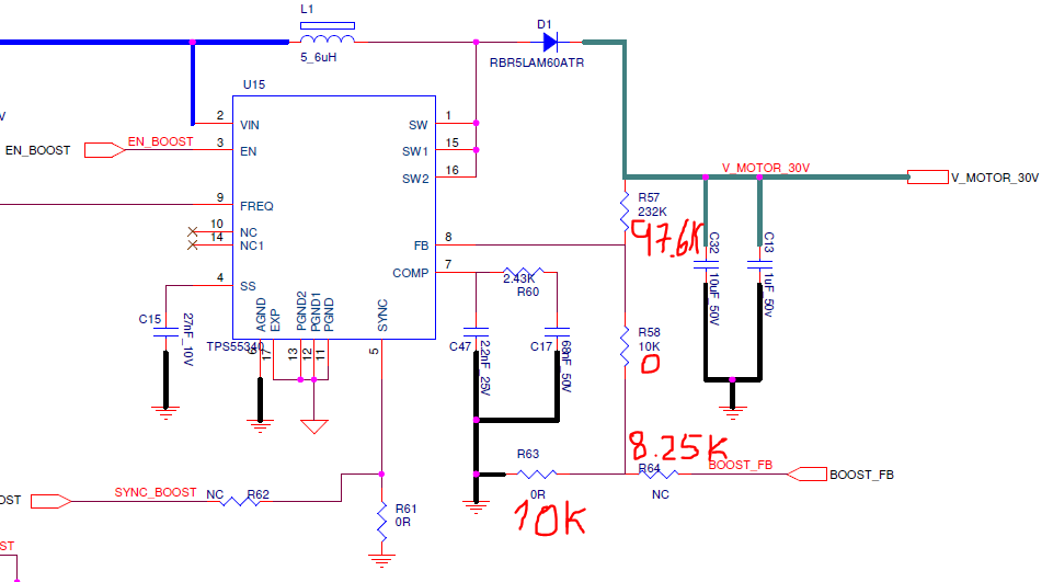
to control the output voltage of the boost by using the DAC from my microcontroller, please let me know what is the correct resistors values.

the DAC range is 0-1.8V

the V_MOTOR  - 6.5V- 28

I received the following resistors values for DAC output 0-3V

When DAC output is 3V, V_MOTOR is 6.5V.

When DAC output is 0V, V_MOTOR is 28V.

Thanks for your help

Hen

  • Hi Hen,

    The calculated upper resistance is 97.6k, the resistance connected to BOOST_FB is 8.25k. Lower FB resistance is still 10k.

  • thank you for the support.

    can you please tell me the calculations made for future use?

  • Hi Hen,

    TPS55340 Vref=1.229V.

    According to KCL equation, (Vout-Vref)/RFBT+(VDAC-Vref)/Rdac=Vref/RFBB.

    RFBT is the upper feedback resistor and RFBB is the lower feedback resistor. Rdac is the resistor connected to DAC output.

  • hi,

    if you have a simulation I can use I'll appreciate it.

    we have changed the resistors to look like the following schematics. this worked great for DAC of 0-3V, and output voltage of 6.5-28V 

    we now use DAC 0-1.8V with the same output. 

    I tried changing the resistors to the following parameters, in 6.5V it's working o.k but the maximum voltage output is 16V.

    please, your guidance to resolve this issue as soon as possible

    thank you

  • Hi Hen,

    Sorry for the late response. I was on vacation last week.

    I don't have a simulation yet. I only use EXCEL and equation (Vout-Vref)/RFBT+(VDAC-Vref)/Rdac=Vref/RFBB to calculate the resistances.

    I have double checked that Vout should be around 28V when DAC output is 0V.

    Have you checked the BOOST_FB is 0V? What's the voltage of FB pin now?

  • Hi,
     we tried your suggested configuration for 1.8V (un our new card) and got a voltage swing of 11V-20V. after verifying the FB voltage is as expected. 
    After that we made changes in our new card to return the Vref to 3.3V and noticed that the voltage gets to 24V for 0V (DAC), as before but that for 3.3V (DAC) and less then 10V input voltage we get 10V output voltage from the boost.
    In some cases (mostly when starting from low voltage), we get lower voltage of about 8V but we couldn’t find any consistency.
    We returned to our old card and found the same behavior there (we mostly worked with higher voltage so we didn’t noticed it before)
    Any suggestions?   


    supposed 

  • Hi Hen,

    What's the difference between old card and new card? Can you share the schematic and layout to me? 

    What do you mean here return the Vref to 3.3V? Do you mean the DAC supply voltage? When you test the new card, have you measured the DAC output, FB pin voltage, Vout pin?

  • hi, our new card has a vref for the micro-controller, of 1.8V

    which means the DAC is 0-1.8V

    the old card, had a 3.3 vref for the micro-controller, and it's schematics is as follows:

    this schematics is not updated. we changed the FB resistors as you requested. the values change from minimum 10V to 25V.

    we changed the resistors in the new card as you calculated. but did't get the wanted values, as described in previous mail.

    we tried using in the new card the resistors calculated for 3.3V, and changed the DAC to 3.3V (I verified that it's indeed what I get in the FB)

    but still the values we see go as low as 10V not less.  

  • Hi Hen,

    Firstly I want to confirm with you, what's the input voltage"MAIN_PWR" when you did the test? Is it fixed 5V or 10V?

    TPS55340 is a non-synchronous boost converter. It means the output voltage is higher than input voltage. When Vout is programmed lower than input voltage, Vout will follow Vin. So if you set Vin 10V, even you want to get a 6.5V at output, the Vout will still keeps at around 10V.

    If you set Vin 5V, it won't be a problem. I hope you can do below bench measurement, it would help me analyze.

    1. Measure BOOST_FB, FB, Vin, Vout DC voltage with a DMM when BOOST_FB=0V and 1.8V.

    2. If you have digital oscilloscope, please probe SW, Vout, FB pins wavefrom.

  • hi, 

    attached are the results as requested in excel file.

    Boost FB test for TI.xlsx

  • Hi Hen,

    Thanks for sharing it.

    The results shows actually the BOOST_FB is not varying from what you said 0-3.3V but 0.485V~2.5V. That's the first reason why output voltage is not what you want after resistors are changed.

    The second reason you have to test the circuit in the condition of Vin=5V, not 12V. TPS55340 is a non-synchronous boost converter. If set Vin=12V, the minimum output voltage will be Vout minus voltage drop of diode. So when BOOST_FB=2.5V and Vin=11.98V, the Vout=11.69V.

    In summary, please tell the exact value of BOOST_FB minimum & maximum value. Test the circuit at Vin=5V.