This thread has been locked.

If you have a related question, please click the "Ask a related question" button in the top right corner. The newly created question will be automatically linked to this question.

TPS62136: Bode plot and stability

Part Number: TPS62136

Hi,

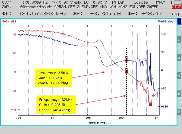
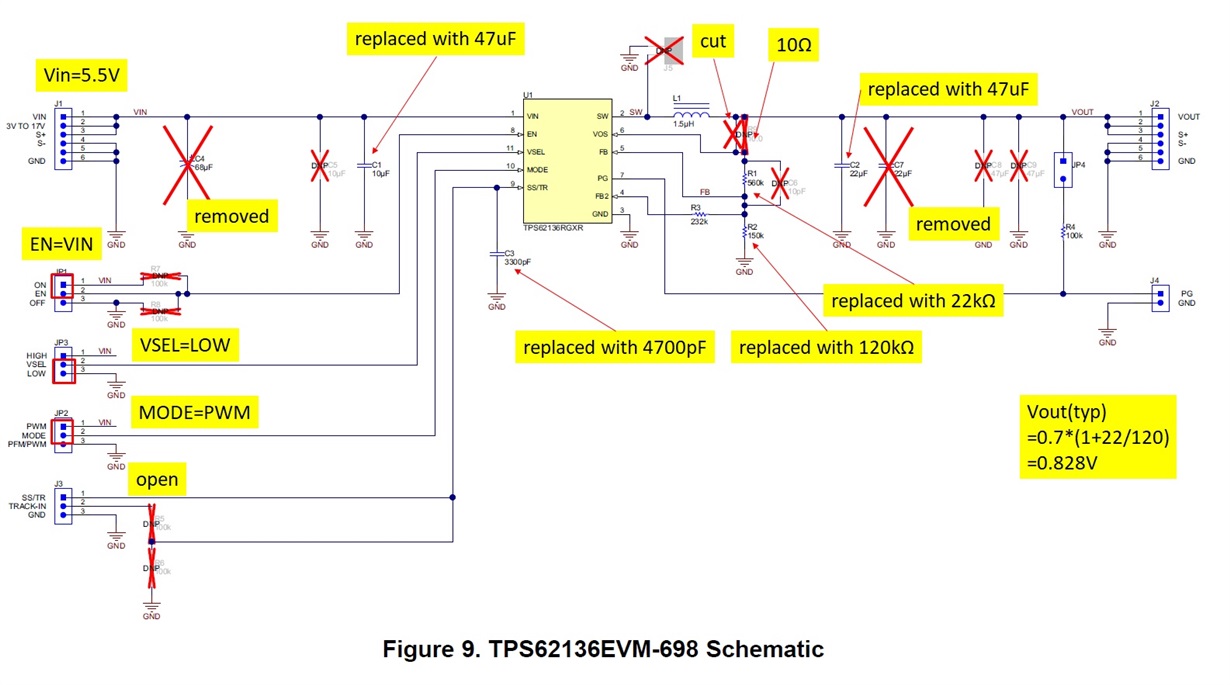
The attached image is the bode plot obtained using TPS62136EVM-698.
The schematic is also attached.

Is this circuit stable and has small over/undershoot at load fluctuation?
If not, please tell me how to improve stability.

The phase at 0dB is about 48deg, and the phase at this point (=phase margin) is considered to be sufficiently large.
However, I think it may be unstable because the phase is as small as about 20deg at around 30kHz.

I have confirmed that the phase margin improves by reducing the value of the output capacitor,
but the output voltage ripple increases and does not meet my requirements (less than 20mVpp at 5.5V-9.5V).
Also, adding Cff seemed to have little impact.

Thanks

  • user,

    It is normal to have a phase dip just above the LC corner frequency as there is a double pole causing 180 degrees phase shift.  With a low value of VOT close to the reference voltage, there will not be much phase boost available with a feed forward capacitor.  The phase boost is proportional to Vout/ Vref.  I do not see any issues with your measured loop response.

  • Hi,thank you for your answer.


    I understand that the phase dip is reasonable and the measurement results are correct.
    Please tell me how to determine if this loop response is OK (= stable?).
    Does it mean that there is no problem if a phase dip occurs at a frequency lower than the crossover frequency?
    Also, please let me know if there are theoretical explanations in reference materials such as application notes.

  • User,

    The loop response looks reasonable and stable.  In absolute terms, the loop is stable if the phase is positive when the gain is 0 dB and when the gain is negative when the phase is 0 degrees.  You will want some margin, hence the terms phase margin and gain margin.  Generally the accepted margins are 45 degrees PM and - 12 dB GM.

    Here are a couple of application notes:

    http://www.ti.com/lit/an/slva465a/slva465a.pdf

    www.ti.com/.../slvae09a.pdf

  • Thank you for your quick answer.
    In this case, a phase dip occurs and it is below 45 degrees, but the (open loop) gain is as large as 20 dB near that frequency, not 0 dB.
    I think this circuit satisfies the stability condition because the denominator of the closed loop gain is not zero.
    Is my understanding correct?

    Sorry for the external URL, but I found such an explanation on the following website.
    www.powerelectronics.com/.../stability-criteria-control-system
    ("Stable or Unstable?" Section)

  • User,

    Yes I think it is fine.