This thread has been locked.

If you have a related question, please click the "Ask a related question" button in the top right corner. The newly created question will be automatically linked to this question.

TPS65218D0: DCDC4 start-up issue on module in production

Part Number: TPS65218D0
Other Parts Discussed in Thread: AM3356, , TPS65218

Dear experts,

We use this PMIC to power AM3356. Two years ago, we reported the same start-up issue in our module with -B0 sillicon revision on DCDC4. Your team recommended us to change PMIC to a new sillicon revision -D0. All affected boards were fixed with 330pF workaround in L4 coil and this problem seemed to be fixed. Currently, we have experienced DCDC4 start-up issues again reported by the client. Reading a lot of posts in this forum, I try to collect all test I think you need.

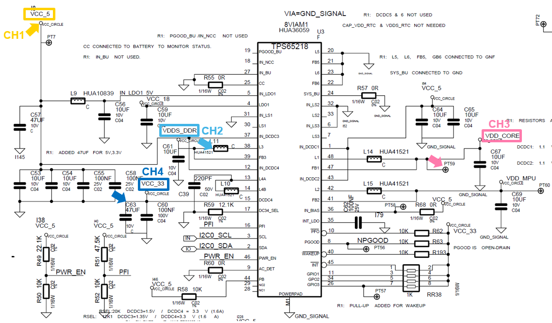
Firstly, PMIC schematic with oscilloscope channel marked for your easy identification.

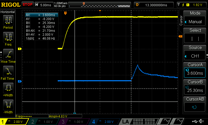
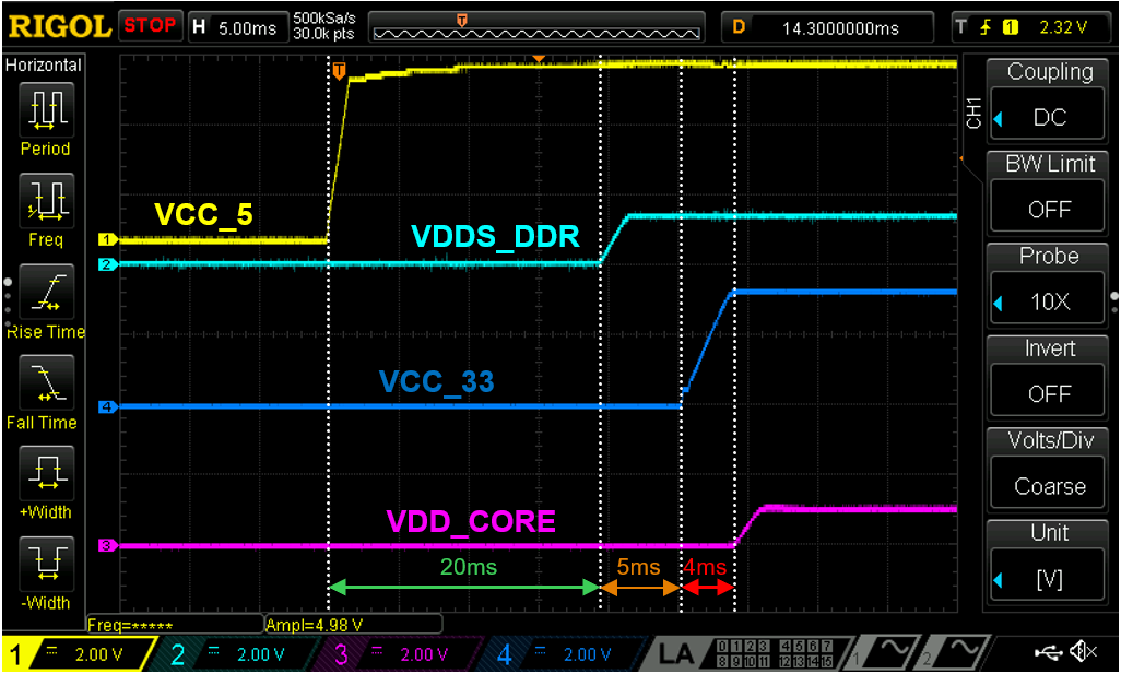
Second, you can see the ocilloscope captures in two cases: Start-up sequence correctly and Start-up sequence failure. These captures were taken in the same module and its performance is fully random.

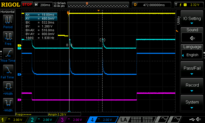
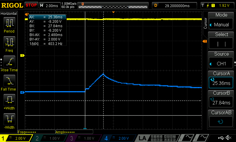
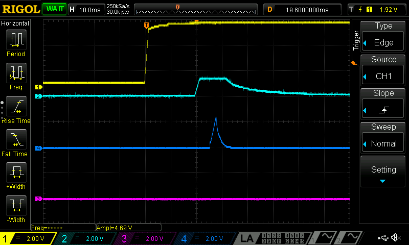
As you can see in above picture, it has 500ms between each retry to power DCDC4 (3.3V). For more information, I put a ocilloscope capture with detail view of this failure case.

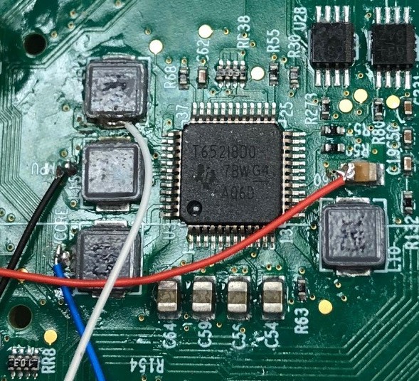
Regarding to pcb layout, We follow the layout guidelines in datasheet: 47uF output capacitance and 1 mm of distance between pad and capacitor.

After that, we think new PMIC sillicon revision (D0) does not fix previous issues detected in -B0 revision. We have observed that some boards seem to start-up even after 8 retries. This performace generates a chained problems many components in our product, including ETH PHY.

My question is: What do you think what is the cause of this behavior? Is there any explanation or root cause for these retries?

Thanks in advance. Don't hesitate to ask any test that you need to solve this issue.

Best Regards.

  • Carlos,

    I have a few follow-up questions:

    • Why do you have C39 (220pF) populated on new board with TPS65218D0? No workaround is required for -D0 silicon.
    • Can you please provide datasheet for HUA41521? I cannot find inductor part number HUA41521 when I search for it.
    • Can you please provide picture showing top-side marking of TPS65218D0 IC on-board? Although you have indicated that you are using -D0 silicon, the schematic still says TPS65218 (not full orderable part #) and I need to confirm which IC is populated on-board

    Other than ensuring that the correct components are used, you could also debug by removing the load from VCC_33, if possible. Separating VCC_33 from the load would let you see if DCDC4 can power-up correctly without any load applied. The 3.3V load is unique because it can supply power to the processor I/O rail but also to many peripheral devices. If the peripheral devices all sinking current for the PGOOD signal is set high, this could be another reason DCDC4 does not power-up correctly.

    During start-up and after a change in voltage, each DCDCx has a "time-out" value of 5ms (typical) before VPG and VOV supervisors are active. If any DCDCx takes longer than 5ms to reach the setpoint, then a fault will be triggered and the power-down sequence will start. I cannot say from the scope shots you provided if DCDC4 is taking >5ms to ramp up before the fault occurs. It would help if you could zoom in further on the 3rd scope shot to see the timing more clearly.

  • Hello Brian,

    Thanks for your quick reply. I'm going to answer your questions.

    1. C39 is not mounted on the new batch. Schematic is not modified due to this kind of issues are managed in BOM assembly.
    2. Yes, of course. This reference is an internal reference of our database. The MPN is SRP4012TA-1R5M of Bourns.
    3. Bellow, you can see the picture of PMIC sillicon version. Wires only has been soldered for test purposes.

    Regarding to 3V3 load debug, it is very complex for us separates device peripherals because there are many components connected to 3V3 power plane. In order to ensure that this inconvenience has not the root cause of one overload condition, it has been added a auxiliary load about 300mA power consumption additionally. In this case, PMIC performances in correct way and after many power reboot, PMIC fails again. So, we think it is not the root cause.

    Currently, we are doing tests about PGOOD and 5ms of ramp that you mention. When we have the result, I will post here.

    Thanks.

    Best Regards,

    Carlos

  • Carlos,

    Assuming DCDC4 is simply taking too long to reach the desired output voltage, could you try changing the output filter in the design?

    As the datasheet says: "Larger or smaller inductor/capacitance values can be used to optimize performance of the device for specific operation conditions."


    DCDC4 should still work with L=1.2 uH and Cout = 33uF.

    In most designs, Cout = 47uF with a voltage rating of 6.3V which is the same as the recommendation in the datasheet (GRM31CR60J476M).

    It is possible that the 47uF (C63) in your design, with a voltage rating of 10V, does not de-rate much when a voltage is applied. In other words, the capacitance may be slowing down the output voltage. Reducing the inductance and capacitance in the output filter could help to ensure DCDC4 reaches 3.3V before the timeout window closes.

    NOTE: this is not the same as the issue which occurred on the TPS65218 -B1 silicon, which essentially did not have any soft start and the inrush current was too high.

  • Hello Brian,

    I come back with tests you asked. Regarding to 5ms of delay to reach 3.3V output voltage, you can see an ocilloscope capture with cursors. The time is 2.4ms when start-up sequence fails.

    We have changed DCDC4 Cout from 47uF to 33uF in our test board used in previous test posted here. Performace seems to be similar to other tests.

    Besides, we have observed this issue is related to temperature as you can see in this attached video. First, we power on the tested board and presents start-up failure explained in these posts. If it applies a freeze spray (CRC minus 50) over PMIC, DCDC4 works instantly. For more information, oscilloscope captures of this video is shown bellow. 

    Thanks in advance.

    Best Regards.

  • Thank you for the updates Carlos.

    It is interesting that cooling down the PCB/PMIC resolves the issue very quickly. What is surprising to me is that DCDC4 turns off before it tries to get to 3.3V for the full 5ms. 2.4ms is not even close. It is also interesting that DCDC4 shuts off when the voltage is ~2.4-2.5V (i.e. a diode drop above 1.8V)

    Did you take any scope shots showing the LDO1 voltage, supplying power to VCC_18 net in your schematic? So far, I can see that VDDS_DDR (DCDC3) ramps up quickly and is stable, but I cannot see what is happening on LDO1. If LDO1 starts to rise above 1.8V (due to an unknown leakage path), the fault would be on LDO1, not DCDC4, which would explain the 2.4ms and point to a different problem.

    Also, how many of these boards were assembled, and how many of them have the issue (% failure)? This is just a common question that we ask for potential quality-related issues.

  • Hello Brian,

    Answering your questions:

    • Bellow, you can see the oscilloscope captures including VCC_18 with slope details.

    • Currently, we have a production about 500 boards with both PMIC sillicon revisions. Our EMS don't have traceability of how many boards has -B1 or -D0. All affected boards that we have analyzed mount -D0. In the other hand, -B1 boards with 330pF capacitor workaround works right until now. We are trying to collect information as much as possible and carry out several tests in climatic chamber to clarify the root cause.

    Thanks & Best Regards.

  • Carlos,

    At this time, the only explanations I have for the issue are manufacturing related:

    1. There is a short somewhere on the 3V3 rail which causes DCDC4 to stop powering-up in <5ms, before the timeout window expires
    2. There is a poor lead/power PAD connection due to re-soldering new -D0 samples. The leads appear to be soldered down OK, but pins 13-24 (and 37-48) appear to be slightly off-center. I cannot see the PowerPad at all, but I know sometimes re-soldering the PowerPad can be very difficult on an SOIC package.

    Aside from this, I can only confirm that it looks like DCDC4 is the cause of the fault but that the issue is not consistent with issues that were observed on -B1 silicon.

  • Note that the spraying of the IC with cold air may be providing improved contact in addition to lowering the temperature locally on the board.