This thread has been locked.

If you have a related question, please click the "Ask a related question" button in the top right corner. The newly created question will be automatically linked to this question.

TPS23881: TPS23881 Auto mode configuration and control registers

Part Number: TPS23881
Other Parts Discussed in Thread: BOOST-PSEMTHR-007,

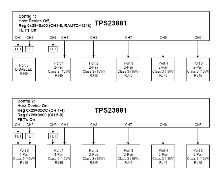
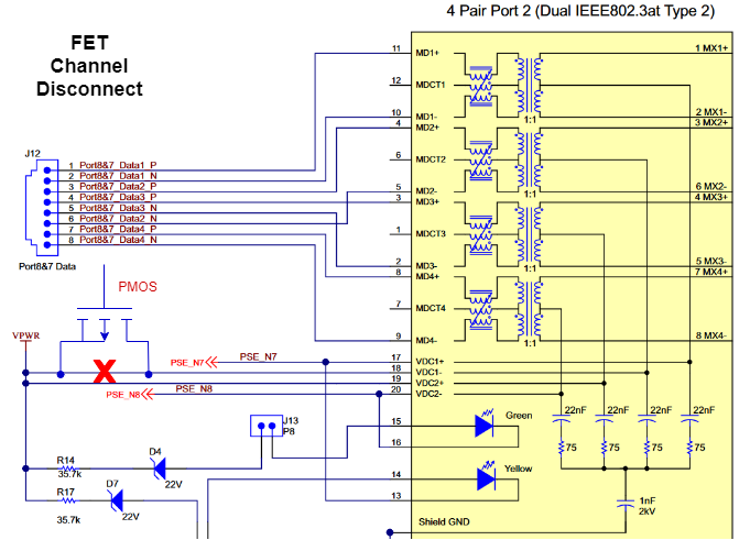
I have some questions about how the TPS23881 will behave in auto mode with the following connectivity (see image) and the AUTO pin set to 124kOhm (2-pair, 15.4W). What will the 4-pair ports (ports 0 & 1) do in the case of: (a)  4-pair Class 5 PD connected (b) 2-pair Class 3 PD connected - assume all 4-pairs connected to PD IC through full-bridge rectifiers. Is there any way to have one of these ports disabled in AUTO mode? Also, some of the control registers (particularly 0x12 and 0x14) seem to only have enough bits to control 4 channels?

  • Hi Dev,

    If you have a mix of 2 pair and 4 pair ports within one device, autonomous mode is not the best option for you as the resistor on AUTO pin sets all ports to the same power allocation. In your case, if you set to 124K, all channels (1-8) are set to 2 pair 15W which means channel 1-2 and 3-4 can't operate in 4 pair mode and will fail detection when connecting to a PD(no matter if it is a class 5 or 3 PDs) because 2 pair ports don't do connection check and there's no control of both pairs to do sequenced detection and classification.  In your case, you will need a host (has I2C bus) to configure the ports to different power allocation (through register 0x29) and still set the ports to auto mode as long as your power supply has enough power to supply all ports(30W*4 + 45W*2 = 210W) and you do't need power management. For the register settings, you have 2 mode to send I2C command: 

    Configuration A (default setting). This means 8-bit access, while the 8-channel device is treated as 2 separate 4-channel devices with 2 consecutive slave addresses

    Configuration B. This means 16-bit access with a single device address (A0 = 0)

    If you configure the device to configuration B, please refer to Table 26 in TPS23881 datasheet.

    You port setup is very similar to TPS23881EVM-008 and BOOST-PSEMTHR-007 (we configure channel 1-4 as 2 pair ports and channel 5-8 as 4 pair ports). We also have MSP430 reference code with auto mode and semi auto mode(http://www.ti.com/product/TPS23881/toolssoftware). Please take a look and let us know if you have further questions. Thanks.

    Best regards,

    Penny

  • I'd like to try this workaround for supporting the following configurations:

    Config 1) TPS23881 will boot in AUTO mode with RAUTO=124k, setting all the ports to 2-pair Class-3 (15.4W). We will have a total of 5 ports in this configuration (Ports 1-5). Both channels of Port 0 and one channel of Port 1 will be disconnected via normally off MOSFET's inline with the 54V connection to the Ethernet magnetics.

    Config 2) System will transition from config 1 to config 2 when our I2C host device boots up and configures the TPS23881. Ports 0 and 1 will be configured to 4-pair, Class-5 (45W) ports by setting register 0x29=0xCC (first slave address) and Ports 2-5 will remain as 2-pair Class-3 (15.4W). Once configuration is complete, the host device will turn on the MOSFET's, connecting power to the previously disconnected channels. All ports will remain in AUTO mode throughout this process (register 0x12=0xFF).

    Some questions I have about this workaround:

    A) Will the inline MOSFET's be sufficient for disconnecting channels? I believe the TPS23881 would behave the same as if there were no device connected to the port (cable left floating), but maybe there will be issues with the PSE seeing an AC impedance through the MOSFET's? I'm not concerned about the additional resistance of these MOSFET's because we have fairly short cable lengths (<10m).

    B) Will there be issues re-configuring Port 1 as a 4-pair port after it has already gone through detection/classification/power-on as a 2-pair port?

    I currently plan on using a host device to configure the TPS23881 before powering on any ports, but this approach could have same advantages for the application (assuming it works reliably). If there are any additional concerns with this workaround, please let me know.

  • Hi Dev,

    My understanding is that you always have 6 RJ45 connectors on the hardware and depending the different configurations, you can enable/disable port 0 and set port 1 to 2pair or 4pair. You always have host available to configure the device through I2C bus. If that's correct, you you don't need to add extra MOSFETs on the port. Instead, you can just disable channel 1,2,3 (configure in OFF mode) in configuration 1 and set channel 4 -8 to class 3 15W (in register 0x29) and auto mode(0x12). In configuration 2, your setting is correct.

    In addition, you don't need connect any resistor on AUTO pin as your configurations can't live with one single setting on auto pin resistor.  You can just leave the auto pin floating and configure the power allocations and set device's operating mode through I2C commands. Thanks.

    Best regards,

    Penny

  • Hi Penny,

    The issue is that I don't have the host available at power up (the system powers on, TPS23881 boots up, but the host does not boot until a later time). Before the host boots and configures the TPS23881, I still want to operate as specified in Config 1 above (5x2-pair ports, Class 3). When the host becomes available, I want to transition to Config 2. That's the purpose of this workaround with the MOSFET's.

  • Hi Dev,

    I got your point.

    Unfortunately, once TPS23881 is initialized in Autonomous mode (ie powered on with a resistor on Auto pin), there is no means for a host disable autonomous operation. Let's discuss with our team and see if there's any workaround for your solution. I will get back to you next week. Thanks.

    Best regards,

    Penny

  • Hi Dev,

    I checked with our team and your workaround should work as long as you load the SRAM code after the host becomes available. After the host is up, you need to do the following to switch the system to configuration 2:

    1. Load SRAM code(you can request access to the SRAM code through TPS23881 product folder)
    2. Disable channel 1-4(as these channels will be switched from 2 pair to 4 pair configuration)
    3. Change the port configurations to implement configuration 2.

    Thanks.

    Best regards,

    Penny