This thread has been locked.

If you have a related question, please click the "Ask a related question" button in the top right corner. The newly created question will be automatically linked to this question.

BQ25504: how to disable the 16sec reset OCV sampling while using the ext Vref MPPT?

Part Number: BQ25504

Hi 

I'm providing the external Vref to BQ25504 and have an external MPPT algorithm.

The 16s  OCV sampling is disturbing my setup and measurements.

Could you please tell me how to disable the 16s periodic OCVsampling without disable the ext reference MPPT operation? 

Thanks & regards,

M. O. 

  • M. O.,

    Please look at section 6 of the datasheet under the pin description for the VOC_SAMP pin. "To disable the MPPT sampling circuit, connect to VSTOR." Let me know if there is anything else I can help with.

    Thanks,

    Ricardo

  • Thanks, Ricardo. When I connect VOC_SAMP to VSTOR, the 16-second sampling does not stop. 

    M. O.

  • From previous trials, when I connected VOC_SAMP to VSTOR, (and provided the VREF_SAMP externally), the dc-dc converter didn't work.

    By trials, I had to keep VOC_SAMP open and feed the external reference VREF_SAMP, however it reset every 16seconds.

    Could you confirm the configuration for MPPT with external reference and without the 16seconds sampling?

    Thanks

  • M.O.,

    Shorting VOC_SAMP will disable the MPPT sampling only. The RDIV sampling cannot be disabled as it is necessary for operation. As for applying a reference to VREF_SAMP I think I may understand your issue. Could you put a 100ohm resistor in series between your power supply and VIN? If you are connected directly to a power supply and trying to regulate the input the power supply will conflict with the IC's regulation. Ultimately the power supply will win and the converter will not work. Adding the resistor will allow for the IC to regulate to your reference value properly.

    Thanks,

    Ricardo

  • Thanks, Ricardo, for your suggestions. Actually I'm using the BQ25504 in a low power energy harvesting. so, it already has an output resistance.

    That 16s sampling event disturbs my MPPT algorithm that I'm trying to do using the ext Vref. Any suggestion to control/shut down/ synchronize that 16s sampling. I don't know even when it happens. I'd shut down the ext MPPT algorithm if I know when that OCV sampling happening.  

    I've posted another question about the response time after setting a new Vref, to measure the new input current to calculate the next Vref?

    https://e2e.ti.com/support/power-management/f/196/t/858313

    Thanks

  • Ouda,

    I am still confused by you are seeing a sample event every 16s. This behavior is indicative of MPPT still being active. Could you confirm MPPT is disabled by measuring the voltage between VOC_Samp and VSTOR? Would it also be possible for you to try to recreate Figure 18 of the datasheet?

    Thanks,

    Ricardo

  • Ricardo, 

    Thank you for your answers.  I noticed before if I disable the MPPT (OCS=VSTOR), the regulation using Vref doesn't work properly until I let OCS floating again.  Another issue, I'm connecting VSTOR=2V to avoid the cold start condition. 

    I've just tried again:

    VSTOR=biased by  (Vs=2V, Rs=100kOhm),

    OCS=VSTOR, however, both connected became ~400mV (not 2V) 

    What is the recommended setup for using external REF, while avoiding the cold start condition?

    Thanks

  • Excuse me for repeating some parts to be clearer.

    For ext MPPT scenario: I set Vref, sense Iin_dc, then calculate next Vref ... how fast could be these iterative steps?

    While searching/iterating for the optimal Vref, Should VSTOR be or reach >1.8V for each iterative step?
    Could I run my ext. MPPT algorithm in the cold start mode? Or I have to wait for the main boost_charger to be on VSTOR>1.8V? 

    Could I connect VSTOR to a 2V while connecting it to OCS to disable the internal MPPT? but both fall down to ~300mV once they are connected!

    Your advice, recommendations and explanations are highly appreciated. 

    Thanks,

    _________________

    Update:

    OCS=VSTOR disables MPPT and also disables the booster chip. Ext. VREF is useless and (VSTOR, OCS) are dead at 330mV!  (even at high Pin,Vin >cold start) 

    I've to leave OCS floating for the dc booster to operate but again the 16s issue... 

    The datasheet is really confusing and disappointing also after designing the system in 2018 based on the early claim it works at 330mV (datasheet 2015-2018)  which is updated in datasheet 2019 showing the reality of 600mV cold start! 

  • Ouda,

    I am sorry to hear that you are disappointed with the product. Unfortunately, we do not warranty performance outside of the boundaries specified in the most current revision of the datasheet. You will have to adjust the operating conditions of your design to fit the device specifications to continue support. 

    If this is agreeable to you, could you please send me a schematic of your system as I am having trouble recreating your issue on the EVM.

    Thanks,

    Ricardo

  • Ricardo,

    I selected the TI chip and built my system in 2018 based on the latest datasheet that claimed a 330mV cold start for years (Since 2015 to 2019). The correction just came up this year 2019 which is really disappointing.

    The second problem in the current datasheet is "connecting OCS=VSTOR will disable the MPPT and allow ext REF to work". However, this is not true and connecting OCS-VSTOR will disable the booster itself and VREF becomes useless, unlike what is mentioned in the latest datasheet. I've observed this issue even at higher power/voltage than the cold start and the VSTOR becomes heavily loaded when connected with OCS and never come up above 400mV!

    My board is the same as the reference board https://www.ti.com/lit/ug/sluu654a/sluu654a.pdf with the same values.  

    My main issue is using the ext REF as fast as possible 

    Thanks, 

    Ouda

  • Ouda,

    Unfortunately I cannot warranty the part's performance outside of the current specifications.

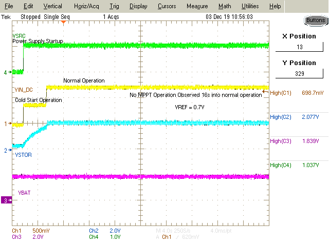
    Outside of cold start I am not seeing any issues with disabling MPPT and applying an external voltage reference. Would in be possible for you to try using a DC power supply with a series resistor to simulate your power source? I would like to see if you can recreate this scope capture of the external reference system working outside of cold start. Please also provide your VBAT voltage.

    Thanks,

    Ricardo

  • Ricardo,

    Thanks for the graph. I guess VSRC is the VSTOR, right? 

    Where is the boosting between Vindc to VSTOR using the external variable VREF? (while VSTOR=OCS to disable MPPT) ?

    could you generate curves for a low Vindc, the boosted VSTOR with different VREF? 

    Regarding warranty: I've designed and ordered my chips in early 2018 based on the datasheets 2015-2018 with the misleading cold start.

    The cold start was just corrected recently in the current datasheet 2019. If a company such as TI can't warranty misleading information marketed for years, who would! Thanks,

    Ouda

  • Ouda,

    To apply an external reference your device must be out of cold start. VSRC is the voltage from my power supply as I do not have access to a solar cell. VIN_DC is what the chip sees at its input. I have labelled my setup in one of the attached images. In the experiments attached I set my power supply to 3V and provided various external reference voltages. In all three cases, the BQ25504 was able to regulate VIN_DC to the desired setting. 

    Thanks,

    Ricardo

    MPPT.zip

  • Ricardo,

    Thanks for the graphs. You are using 5V, R100 source with available Pin=(Vsrc^2 / 4/ R)=62.5mW that's huge input power and a very high input voltage, is this a dc boosting? 

    My design is based on the TI reference board https://www.ti.com/lit/ug/sluu654a/sluu654a.pdf  with same specifications. You may test on the board if you have it. 

    I'm interested in the "boost" converter raising to 3V as specified in the TI reference board.

    from a low power source >  Pin=15uW (the latest cold start points)

    Could you please repeat your last experiment using a power source Pin =20uW ( emulated as Vsrc=1V, Rsrc= 10k Ohm) 

    and find the optimal Vref to get the maximum power?  while connecting OCS=VSTOR

    -side question: from the TI reference design board, is it correct to connect OCS=VSTOR to use external VREF?

    This still pulls down my VSTOR and makes the VREF useless, again I had to let OCS float to operate. (Is this correct to let OCS float and provide a variable VREF? you know the 16s OCS is happening in the case. 

    Thanks

    Ouda

  • Ouda,

    In my experiments my device is seeing small voltages at the input (1V, 0.7V, and 0.6V) and boosting up to 3V at VSTOR. The device is operating as a boost circuit. I am using the same reference board you have linked. I have positioned JP1 so as to short OCS and VSTOR in my experiments to disable MPPT.

    It is up to you as the customer to determine the optimal VREF value for your specific energy source. If you provide me with that value I will be happy to recreate it to the best of my ability in the lab and provide you with my results to compare to yours.

    It is acceptable to short OCS and VSTOR to disable MPPT while applying an external voltage to VREF.

    Thanks,

    Ricardo

  • Ricardo,

    Thanks for your reply. As I pointed before your power source is 62.5mW.

    Could you emulate a lower power source (1V, Rs=10k, Pav=20uW)? This setting is working using the internal MPPT with resistive ratio but does not work with ext VREF  while OCS=VSTOR. 

    Thanks,

    Ouda

  • Ouda,

    Unfortunately I will not have access to the lab this week. Would it be possible for you to try this in the lab and send back an oscilloscope capture>

    Thanks,

    Ricardo

  • Hello,


    I have not heard back from you in a while. Please let us know if you have any further questions, otherwise I will be closing this thread.


    Thanks,

    Ricardo

  • Ricardo,

    I'm waiting for your response to my request: 

    "As I pointed before your power source is 62.5mW.

    Could you emulate a lower power source (1V, Rs=10k, Pav=20uW)? This setting is working using the internal MPPT with resistive ratio but does not work with ext VREF  while OCS=VSTOR. "


    could you please emulate the lowest possible power supply: Pav= Vsrc^2/Rsrc/4 

    could you show the chip can fully charge the VSTOR (>2.8V), while VSTOR is tied to OCS? because this never happened with me. Please don't use that large power supply you used before 62.6mW is too much.

    Thanks

    Ouda


  • Ouda,

    I have recreated your setup to the best of my ability using Rsrc = 75k. I am not seeing any issues. On the scope shot where I show VSTOR charging up to 3.28V I disconnected the battery to speed up the charging process as the VSTOR cap behaves as a small, quick charging storage element. 

    Unfortunately I will not be able to assist further without scope shots from you or further information about your setup.

    Thanks,

    Ricardo