This thread has been locked.

If you have a related question, please click the "Ask a related question" button in the top right corner. The newly created question will be automatically linked to this question.

UCC28951-Q1: The duty cycle of Vds will decrease when the shunt down

Part Number: UCC28951-Q1
Other Parts Discussed in Thread: UCC28951

Hi team,

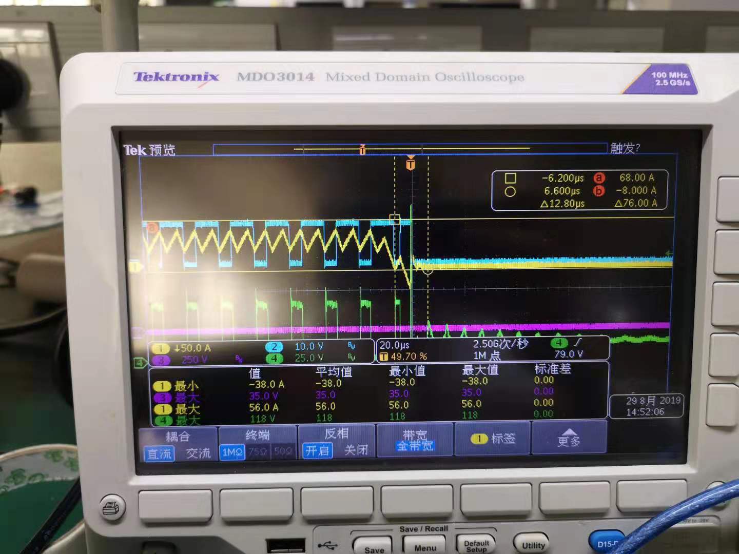
my customer use UCC28951-Q1 and have an issue is that when the shunt  down, the duty cycle of Vds and gate driver signal will decrease ,please see the below picture.

The Blue is Synchronous rectifier driver signal, the Yellow is inductor current and the Green is Vds. 

You can see that when the current goes down, the duty cycle of driver signal will decrease and there will have a overshoot on the VDS. 

The problems are that:

1. why the duty cycle will decrease?

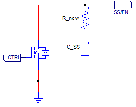
2. In customer application, when the pull low the SS/EN pin, the comp pin will also been low, we think it may cause the duty cycle change. So, they  want to know what's the relationship between phase shift angle and comp pin voltage ? do you have more clearly description about this?

Thank you.


  • Hello Betty

    The voltage overshoot happens because the current in the SR is negative or flowing from drain to source when the SR is turned off. There is a two cycle counter on the DCM logic so that when the current drops below the DCM threshold the system waits for a second cycle before disabling the SRs. If the SRs are disabled before the inductor current becomes negative then the SRs will behave as diodes and this will prevent this over voltage spike because the current in the diodes can not flow in the negative direction (from Cathode [Drain] to Anode [Source])

    The UCC28951 will stop all switching activity immediately (withing 1 or 2 us) when the SS/EN pin is pulled below the stop threshold of 500mV nominal. So, quickly pulling SS/EN low would be a way to prevent this spike.

    Alternatively, the energy in the spike could be clamped by a TVS diode.

    The phase shift angle and COMP voltage have a linear relationship. Lower COMP voltages give a smaller duty cycle, larger COMP voltages give a wider duty cycle.

    Can you give more details about the load transient - it looks like it goes from full load to 0 in a few microseconds.

    Regards
    Colin

  • Hello Betty

    A final comment - I agree - the duty cycle is decreasing because the COMP voltage has decreased.

    Regards

    Colin

  • Hello Colin,

    Thank you for the info.

    This issue is from my application. We use an external error amp accually, the internal error amp of ucc28951 is connected as voltage follower. The issue happens when turn the chip of ucc28951 off by pulling SS down. Because the internal error amp is connected as voltage follower, the voltage on COMP will decrease as the SS is pulled low. The falling time of SS voltage (and the COMP voltage) is around 2~4 micro sec, sometimes we can see phase shift angle significantly changing when SS and COMP falling. Then the inductor current is effected, and cause an overstress of MOSFET.

    There's a cap tied to the SS pin to adjust softstart time, now it's difficult to reduce the falling time of SS and COMP voltage. So we need to evaluate how the phase shift angle associated to the SS voltage (and COMP voltage)  WHEN THE VOLTAGE IS FALLING in 2~4 us. 

    The switching frequency of ucc28951 is ~65kHz, we can see the change of phase shift angle varies when SS voltage falling at diffirent time of  the period.

    There might be some logic gates and flip-flops in ucc58951, it's better to see a more detailed block diagram of the chip. and Please help to find out how we can calculate the phase shift change when COMP voltage is falling. Thanks.

    Regards

    Preston Wang

  • Hello Preston

    Here are some results I took showing how the OUTx signals react when the SS/EN pin is pulled to zero.

    /cfs-file/__key/communityserver-discussions-components-files/196/SS_5F00_EN-pin-response-speed.docx

    The key point is that the SS/EN pin controls the duty cycle only during the soft start process. Once the SS process is completed the SS/EN pin is pulled high to about 4.5V or so. Then, if SS/EN is pulled low by an external circuit it does not affect the duty cycle at all until SS/EN reaches about 500mV at which point all OUTx switching stops immediately and asynchronously. (This is different to the current limiting hiccup behaviour shown in Fig 42 of the data sheet because the controller is not in the ILIM condition.)  

    Anyhow, the SS/EN pin will not affect the duty cycle as SS/EN is being pulled low. Here's the relevant plot - it's in the .docx file too.

    Yel: OUTA, Red: OUTB, Blu: SS/EN, Grn: Transformer primary

    So, if the duty cycle is dropping in your application then it is because the output of the error amplifier is driving COMP low at the same time as the SS/EN is being pulled low but I think that these are independent processes. Can you post a plot showing the waveforms in the image above on your application please. Could you also send a plot showing SS/EN, COMP, and the inductor current (Yellow trace in the first image you sent) - I'll  double check the behaviour on my EVM.

    The on-board error amplifier is simply a voltage follower so its output will do whatever its input does. BTW, there are no problems associated with using the on-board error amplifier as a voltage follower.

    There are a few options you might want to think about

    1/ Add a TVS diode to clamp the voltage spike to a safe level.

    2/ Reduce the bandwidth of the feedback loop so that the error amplifier cannot react so quickly

    3/ You should be able to reduce the fall time of SS/EN by placing a small resistor in series with the SS capacitor - can you try this to see if you can pull SS/EN down more quickly. ? like this

    Please send me the plots and I'll try to reproduce them here.

    Regards

    Colin

  • Hello Colin,

    Thanks for your help.

    We've checked our design again, and found out that the output phase change at ucc28951 turning off comes from the error amp, not the SS pin, just as you said. It's a missunderstanding that we thought the SS pin would always effect the output phase or duty. Sorry for that. But I didnot find any specific description about this from the datasheet.

    The phase shift change when shut ucc28951 down is because that the external referance of the feedback loop is pulled low at the same time when driving SS low. This product is designed by someone else. I ignored the external referance change when I do the trouble shooting.

    We've tried to add a resistor in series with the SS cap before, and it helps. But this design is on mass production, the resistor or the TVS you mentioned is not applicable. The final solution is that we modified the feedback loop and the firmware of an associated MCU. There's no significant duty cycle change at shutdown now. 

    Thanks a lot.

    Regards

    Preston

  • Hi Preston

    I'm glad that you were able to solve the problem. I'm going to close the thread now but you can open a new linked thread if you want to.

    Regards

    Colin