This thread has been locked.

If you have a related question, please click the "Ask a related question" button in the top right corner. The newly created question will be automatically linked to this question.

BQ2000T: Configuring the TS input to the bq2000T for ⊿T/⊿t Termination

Part Number: BQ2000T
Other Parts Discussed in Thread: BQ2000

Hi Team,

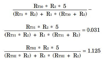
I have a question about "page 7 Configuration the TS input to the bq2000T for ⊿T/⊿t Termination" description in following link.

I read it but I couldn't understand what it explains.

What does 0.031 and 1.1125 stand for in equation in page 7?
What is RT2 value?
does this calcualation affect R1/R2 value?
What does this session want to explain in the first place? how to choose thermistor?

Regards,
Kai

  • Hi Kai,

       The 1.125, and 3.875 values are derived on the previous page (page 6). The deltaT/deltat termination condition corresponds to 31mV/min at 5V supply (0.031 value), and from this equation, the 1.125V value is derived. I do not see where RTH2 is, but RTH1 is referring to the high temperature cutoff resistance.

  • Hi Kedar,


    Sorry but not RT2 but RT3.

    still unclear...
    I know your comment is coming from page 7 and I can read it but I couldn't understand that detail.
    From following equation, we can get 0.031 value and this is leading 31mV/min with a 5V VCC voltage (VCC/161).

    What does this 31mV/min mean?
    if we take this at face value, 31mV increases per min.
    where is starting voltage of 31mV and when is starting point of minutes?

    from following test condition(R1/2 datasheet figure 11), TS voltage at 0C(RC=2.449k) is 0.1496V.
    if 1C increases from 0C, 31mV*1=31mV increase? 0.1496V+0.031V=0.1806?

    This is odd since TS voltage should decrease when temperature increases.

    R1=12.4k
    R2=20k
    thermistor=102AT
    thermistor temp range=0~85C
    RC=2.449k
    RH=0.1751k

    R2||RC=2.182k
    R2||RH=0.1736k

    TS voltage min = 0.1736k/(12.4k+0.1736k)=0.0138
    TS voltage max = 2.182k/(12.4k+2.182k)=0.1496

    Also how does 1.125 values is used?
    in addition, regarding following comment, what does "range of 0 to 40C with 1C/min senstivity at 30C" mean?
    does this mean it takes 1min to increase from 30C to 31C?
    if so, how do i think 0~29C and 32~40C?
    "Selecting a low beta thermistor such as the Semitec 103ET-2 together with a 40°C cutoff affords a range of 0 to 40°C with a 1°C per minute sensitivity at 30°C. "

    anyway, I couldn't understand "configuring the TS input to the bq2000T for ⊿T/⊿t" explanation so please explain with more easy explanatnion.

    Regards,
    Kai

  • Hi Kai,

        ⊿T/⊿t termination for NiMH is a termination condition in which temperature of NimH cell is monitored to determine full charge. Essentially slightly excess charging of NiMH is converted to heat and dissipated which is why deltaT/deltat (termperature change) is a valid NiMH termination condition.

    5 degree C over ambient temperature was selected as a valid temperature delta for BQ2000T to assume NiMH termination, and this correspondeds to a ratio dependent on VCC i.e when there is a -VCC/161 +/- 25% tolerance V/min change on TS, then  ⊿T/⊿t termination is detected. (These values are form EC spec) For V/min we are talking about ⊿V on TS not 31mV increase on TS voltage. You are right that with an NTC if temperature is increased, it will correspond to lower voltage on TS.

    30C corresponds to this 5C above ambient temperature, so sensitivity of thermistor should be fairly accurate to guarantee that when BQ2000T samples TS, that it will be able to sample the 31mV delta that would correspond to termination. A thermistor’s beta value, is an indication of the shape of the curve representing the relationship between resistance and temperature of an NTC thermistor. The 40C corresponds to the cutoff temperature, so when temp at 40C, the voltage on TS would correspond to VTCO. It is not 0-29 and 32-40.

    During fast charge, BQ2000T samples the TS pin voltage every 8 seconds and compares it to the value measured 2 samples earlier. 

  • Hi Kendar,

    I got following additional questions so could you help?

    If you have any questions or something you don't understand, please let me know.

    [Question 1]
    There are three bq2000T typical schematics in datasheet, apps note and user’s guide but every schematics has different components/value/connection.
    With following requirement, which circuit is recommended ?
    - datasheet page 13 figure 11.
    - apps note page 9 figure 12
    - user’s guide page 5 schematic

    >Requirement
    Input voltage range: 12(~16)V
    Charging current: 840mA
    terminal voltage: 8.4V (2s Li-ion), 10V (6s Ni-MH)

    And considering heat generation, Q1 thinks that it is better to select FET as in User’s guide.
    Is this idea correct?

    [Question 2]
    Could you let me know the purpose of external components around high side fet?
    e.g) User’s guide has D5/ Q2/ R12/ D7/Q3 and how does these components works how to select these value?

    [Question 3]
    How to select Q1(HS switch), L1(inductance) and C5(Cout)?

    [Question 4]
    From datasheet page 11, charging current is calculated by IMAX=0.05/RSNS.
    However, charging current in EVM is 0.83A with 0.05Ω_RSNS.
    IMAX should be 0.05/0.05=1A but actually 0.83A.

    Could you let me know the reason why charging current is not 1A in EVM?

    [question 5]
    VSLP typical value is Vcc-1 so when VCC=5V, VSLP=4V.
    When we put RB1=320kΩ and RB2=100kΩ to set 8.4V terminal voltage(8.4V*100/420=2V_VMCV), VBAT voltage with 12Vdc_input(battery absent) is 12V*100/420=2.86V.
    This means always VBAT < VSLP so bq2000T doesn’t go into sleep mode.
    In this case, does bq2000T do battery detection?
    (I think it is the case of “VMCV <VBAT <VSLP” in the flowchart of data sheet p.4.)

    [Question 6]
    2s Li-ion terminal voltage is 8.4V so 6s Ni-MH terminal voltage has to above 8.4V to charge Ni-HM.
    From datasheet page 13 “RB2=RB1/(N-1)”, select RB1=320kΩ and RB2=64kΩ but bq2000T didn’t detect battery absent.
    12Vdc_input / RB1 = 320kΩ / RB2 = 64kΩ → Battery voltage of above12V (2 * 384/64) is necessary for VBAT to be above 2V.
    In this case, do we need to increase RB2 value from 64kΩ?
    At least the Ni-HM terminal voltage needs to be 10V or more, so I think that the RB2 value needs to be set within the range of the battery voltage from 10V to below12V.

    Regards,

    Kai

  • Hi Team,

    This is kindly reminder.

    Please let me know if you need any information about above questions.

    Regards,

    Kai

  • Hi Team,

    This is kindly reminder about above questions.

    Regards,

    Kai

  • Hi Kai,

      1) BQ2000 user guide from EVM is a fully validated solution, and it is better to start off with this configuration and understand design considerations before moving on to the application note. The app note details external circuits for different applications of BQ2000/T. Yes the MOD pin drives the gate of the PFET, and BQ2000 can operate as an asynchronous switching charger 

      2) D7 and Q3 are providing the gate drive signal for the high side FET, as it needs to invert the signal from MOD pin to gate of Q3 (Q3 is a PFET).  D5/ Q2/ R12 is to provide quicker turn off of high side FET

    3) If application is not changing much from EVM operation, then it is best not to change too much. Choosing inductor depends on duty cycle, desired inductor ripple current, DCR and switching frequency. You can refer to section 3, and 7 of this app note for equations on inductor and output capacitor selection: 

    4) IMAX depends on VSNS voltage of 50mV (this is where numerator of 0.05 is obtained). Once voltage sensed on this pin < -50mV spec (charge current is sensed as voltage on VSNS pin across RSNS) Datasheet specifies +/-10mV tolerance on VSNS so theoretically you can expect between 800mA and 1200mA IMAX. This is an old part, so it is to be expected that charge current accuracy is not as high as our newer parts.

    5, 6) From datasheet: In a mixed-chemistry design, a common voltage-divider is used as long as the maximum charge voltage of the nickel-based pack is below that of the Li-Ion pack.

  • Hi Kedar,

    Regarding following comment, it seems bq2000T has 20% variation from 1000mA(800mA to 1200mA).

    Do you have any variation data for it?

    4) IMAX depends on VSNS voltage of 50mV (this is where numerator of 0.05 is obtained). Once voltage sensed on this pin < -50mV spec (charge current is sensed as voltage on VSNS pin across RSNS) Datasheet specifies +/-10mV tolerance on VSNS so theoretically you can expect between 800mA and 1200mA IMAX. This is an old part, so it is to be expected that charge current accuracy is not as high as our newer parts.

    Regards,

    Kai

    4) IMAX depends on VSNS voltage of 50mV (this is where numerator of 0.05 is obtained). Once voltage sensed on this pin < -50mV spec (charge current is sensed as voltage on VSNS pin across RSNS) Datasheet specifies +/-10mV tolerance on VSNS so theoretically you can expect between 800mA and 1200mA IMAX. This is an old part, so it is to be expected that charge current accuracy is not as high as our newer parts.

  • Hi Kai,

       No we do not have any variation data on this. Again this part is old and has limited resources available.