Hi
Power rail random failed_ No output, failure rate: 4/100
Following waveforms are normal and fail, What condition will cause VCC on output?
[Normal waveform]
[Fail waveform]
This thread has been locked.
If you have a related question, please click the "Ask a related question" button in the top right corner. The newly created question will be automatically linked to this question.
How are you ensuring the absolute maximum input voltage of the device is not being exceeded?
Can you share schematic?
The VIN of IC pin is direct from 12-V automotive battery, and we have UVP(6V), OVP (28V)function on the battery side.
The VIN on the waveform is around 12V, no more than the absolute maximum input voltage.
Sorry, we can't post schematic.
I have questions as below
1. What condition can cause VCC no output?
2. Why I just provide VIN=12V (EN=0V) VCC can rise to 1.18V
12V battery can have transients that must be handled to assure device absmax is not exceeded.
Long wires connected to DC/DC can cause inductive ringing that can cause device absmax to be exceeded.
ABSMAX violation I would think would be the number 1 reason for VCC to not be normal value.
Have you been able to capture the failure, with waveforms of both VIN and VCC?
Please send schematic and layout to me at my personal email: m-beck1@ti.com
Hi
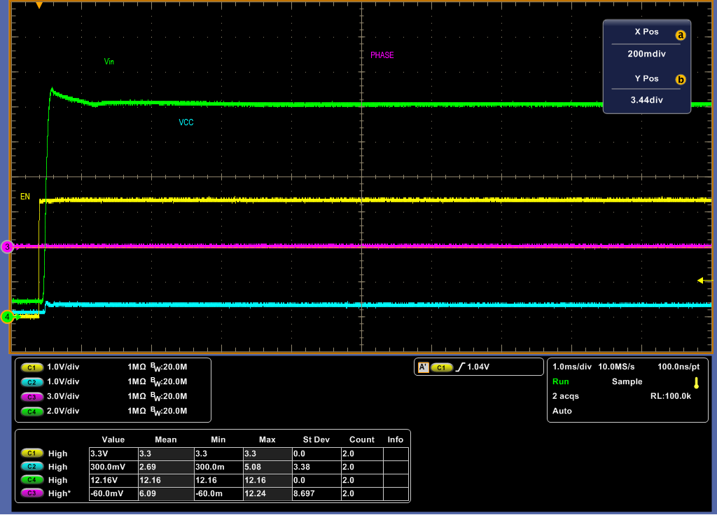
Why you ask 12V transients problem? We are use power supply for testing/debugging this issue. Not Battery. You can see the Vin max ~13V from the waveform.
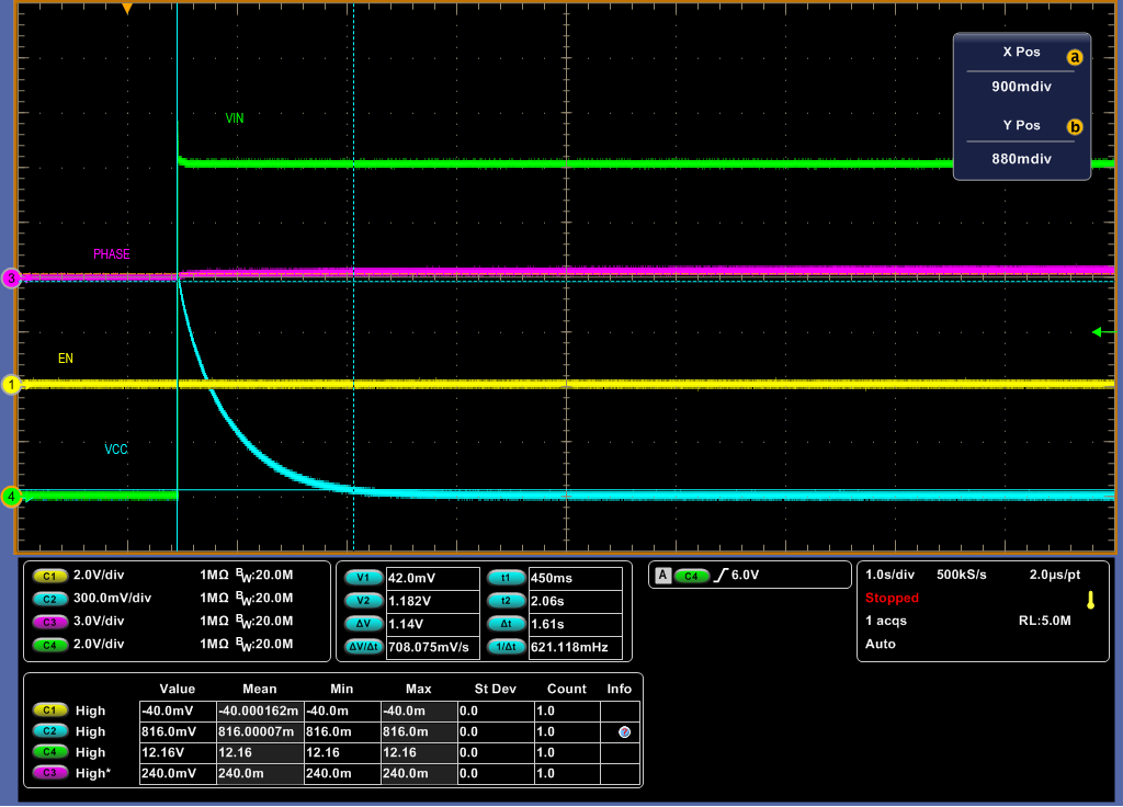
The failure waveform of both VIN and VCC already attached before. So we want to know why VCC can't power on while Vin and EN are ready? in the other words, what kind of condition will cause VCC can't power on?
Due to NDA with customer, we can't provide schematic and layout to you. You can check with TI TW FAE Allen(allen_lee@ti.com). Thanks!
Regards,
Hsing
Hi
Please see attachment. We list 3 questions and attached waveform for your check.
Regards,
Hsing
I understand the issue with sharing information over public forum.
You can email me at: m-beck1@ti.com