Dear Sir.
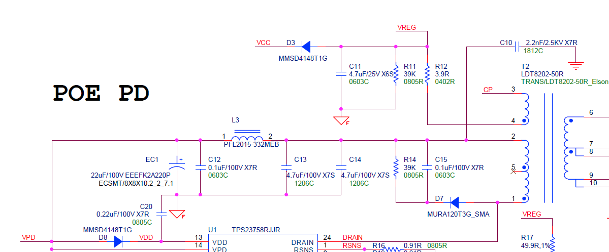
We are currently experiencing a problem. The capacitors in front of or behind L3 will Broken one of them.
It will happen when the board is powered on for the first time. What is the reason?
In addition. What is the role of L3 here?
Dear Sir.
We are currently experiencing a problem. The capacitors in front of or behind L3 will Broken one of them.
It will happen when the board is powered on for the first time. What is the reason?
In addition. What is the role of L3 here?