This thread has been locked.

If you have a related question, please click the "Ask a related question" button in the top right corner. The newly created question will be automatically linked to this question.

UCC28C42-Q1: Schematic Review

Part Number: UCC28C42-Q1
Other Parts Discussed in Thread: PMP10833

Hi Teng,

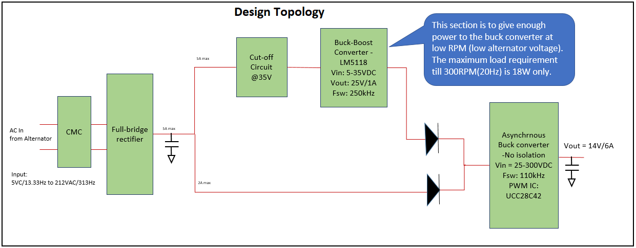
Can you please help me for reviewing the schematic attached?EFI_REGULATOR_BUCK_Schematic_VER_0.1_03Feb2020.pdf

Please review the buck converter in detail along with the component selection. This schematic is based on the PMP10833 EVM design.

Below is the requirement specifications,

  1. Vin:  5VC-212VAC (from alternator) - V_OR_OUT is the input voltage to buck converter after full bridge rectification of Vin
  2. Vin Frequency : 13.33Hz-300Hz
  3. Vout: 14VDC
  4. Maximum load: 6A
  5. Isolation requirement : No

Below table shows the Input Vs Output characteristics,

Input

Freq

Vin

VAC

Vout VDC

IL (A)

13.33

9.40

14

0.80

20.00

13.50

14

1.40

26.67

17.50

14

2.00

33.33

21.90

14

2.40

66.67

47.00

14

5.00

100.00

76.50

14

5.00

133.33

94.20

14

5.50

166.67

122.80

14

5.50

200.00

141.80

14

5.50

240.00

169.90

14

5.50

266.67

187.90

14

5.50

280.00

197.20

14

6.00

300.00

210.90

14

6.00

Regards,

Ajmal 

  • Hello Ajmal,

    You will not be able to use a buck regulator to generate 14V out with an input range of 5V to 212V AC

    This is too wide an input range and the input voltage needs to be greater than the output voltage

    Regards

    John

  • Hi John,

    Thank you for the reply.

    I have missed my complete topology in the previous thread. Sorry for that, Please find the below diagram shows the design topology. So the buck will get minimum input of 25V and maximum of 300V (215*1.414). Please review the buck section including the components selected.

    Regards,

    Ajmal

  • Ajmal,

    If you wish to design a buck converter to operate from 25V to 300V input with a 14V output then the duty cycle is going to vary from 5 microseconds to 0.45 microseconds. It is possible to do this but the switching losses will be high because of the 300V and 6A rating for the FET and also the diode.
    Also the recovery losses of the diode will be high.
    This is the big disadvantage of a very wide input voltage.

    Regards

    John

  • Hi John,

    Thanks for the valuable comments!

    As per the design requirement, system should not use any transformer in the design. So I could not bale to find any other solution than the classic buck converter. That is the reason of using this topology.

    I am not considering the flyback  topology as transformer is involved.

    Regards,

    Ajmal