This thread has been locked.

If you have a related question, please click the "Ask a related question" button in the top right corner. The newly created question will be automatically linked to this question.

TPS2372-4EVM-006: AutoClass Function

Part Number: TPS2372-4EVM-006
Other Parts Discussed in Thread: TPS23881, TPS2372

Hi,

TPS2372-4EVM-006 is support AutoClass function which defined in 802.3bt spec. From what I know, the function of AutoClass is use to detecting actual power at port PI and re-allocate power afterward, which is quite similar to the dynamic mode of power management, isn't it? What's the difference between these functions?

Furthermore, there are few ways to achieve AutoClass according to 802.3bt spec, apart from physical layer AutoClass, it is also possible to request an AutoClass measurement from the PSE by using LLDP protocol. This allows the PD to use AutoClass, even if it is unable to meet the physical layer AutoClass timing requirement to enable the PD maximum power draw immediately after power up since device is in booting stage. I'm not sure about how it works via LLDP, could you please explain for me?

LLDP protocal is based on TLVs which probably is a kind of protocol for MDI interface between PHYs, I guess. I am confusing how does the PSE and the PD communicate with each other via MDI interface since TLVs will be recognized by PHYs instead of both the PSE and the PD?

Thank you.

  • Hi Steven,

    Yes it is similar to a PSE having power management. However, it relies less on needing LLDP and more hardware based to give a path for applications that do NOT rely on LLDP to have some power management functionality. Particularly in lighting applications where the lighting ballast will output full power when it is first turned ON before it goes to a lower power mode.

    Autoclass through LLDP is relatively straight forward in which the PD will let the PSE (through the ethernet data) know that it will output max power. The PSE like the TPS23881 has a function that allows the PSE IC to do autoclass when it is enabled. The micro on the PSE will simply enable this to the PSE through I2C and let the PSE take the current measurement.

    For LLDP protocol, you are right. The PSE and PD chips themselves do not process the data. It is the PHY and MAC and microcontroller on PSE and PD end equipments themselves that process the ethernet data controller either the load (for the PD) or the PSE chip (for the PSE). The PD and PSE merely process the power.

    Regards,

    Darwin

  • Dear Darwin,

    For the more detail of LLDP protocol, I would like to know how does the LLDP works between two switch devices.

    Which way they communicate with each other, by hardware mechanism or software control?

    Is it processed automatically or software polling?

    Thank you!

  • Hi Steven,

    This is a great question but unfortunately this is more related to the ethernet data specifically while my focus is more on the power side of PoE. At a high level though, any ethernet device (PSE switch and PD loads) can connect to a network. Data packets can be sent addressed to specific devices to do certain functions.

    However, I recommend talking with the ethernet PHY forums for more detailed discussions on the ethernet protocols.

  • Dear Darwin,

    I see, appreciate of your help anyway, I will focus on the PoE question and hope you could keep helping me out.

    For the more questions about AutoClass, I saw a new feature of 802.3bt named "Extended Power" in a third party white paper. I'm not sure if this is relates with AutoClass and wondering if you heard of this before cause I found nothing about Extended Power in the 802.3bt spec.

    Following is the part of description of third party white paper, "The extended power feature is to allow the PD or the PSE to use maximum available power based on the cable's true total resistance.Once  the PD measures the cable resistance, it can calculate the power that will be lost on the cable and benefit from a higher power consumption.".

    I got a question came out of my mind after I seeing this that how does the PD or the PD know the cable length? The cable power consumption must be calculated by cable length and cable resistance, is there any LTV could read the cable length? Or is there a way to achieve what the feature described above via LLDP LTVs?

    Thank you!

  • Hi Steven,

    Extended power is not related to the Autoclass function. It was made to allow designers who have control of the entire PSE->cable->PD system. This means the designer knows the output voltage/power of the PSE, the cable length and resistance (maybe it's a custom cable), and the PD power draw. For instance, if the end system knows that it will always use a short cable (not 100m) or forces the end user to use a specific cable (CAT6) then they know greater than 70W will be available at the PD so they design the PD to draw 85W. This is still a hardware approach to greater than 70W at the PD.

    In addition, the idea was that in the future, a system may eventually be smart enough to calculate the cable length (with 'smarts') like what you are alluding to. That I know of, this has not been done yet.

  • Dear Darwin,

    I've checked with third party about the Extended Power, they told me there is a register can be set for extended power based on maximum allowed class power. So I think you're right about the Extended Power that the function is for the designer who knows the entire system and the designer is allow to adjust the maximum allocate power of the PSE for the PD power draw. Your explanation help me to get more understand about this feature.

    One more question, does the EVM of TPS23881 supports Extended Power feature that I might could adjust the maximum allocate power on GUI? I don't receive the EVM yet and I wonder if I can demonstrate this once I get the EVM.

    Thank you very much!

  • Hi Steven,

    The TPS23881 can be adjusted for up to 1.25A per channel (through the GUI). So in a four-pair system you can get (2x1.25A)x50V = 125W or higher depending on the PSE output voltage.

    Thanks!

  • Dear Darwin,

    I have a question about the PSE and the PD behavior that shut off power sourcing while the Power draw is over the limits of assigned class.

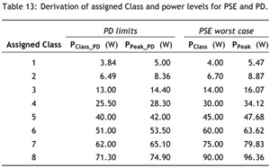
    For instance, presume there is a Class8 PD which maximum power draw is around 80W. According to below table, the PCLASS_PD and PPEAK_PD both are smaller than 80W, which means the PD is designed but out of the spec of 802.3bt. If connect this PD to a Type4 PSE with a short cable, which cable is ideally and without any consumption. In this case, does the PSE supposed to shut off the power sourcing because the PD power draw over than the spec defined?

  • Hi Steven,

    the PSE will protect itself if the power at the PSE exceeds 90W. So 80W with a short cable will not trigger the PSE. So if you have control over the length of the cable in your system then it is okay. Many times a product will bundle the PSE(injector) and cable with their PD end equipment in an attempt to control the overall PoE system (custom PoE system).

    However, if you expect an end user to use a 100m cable, then 80W at the PD, and a PSE that outputs the minimum PSE voltage can trigger the PSE to protect itself. In cases where there is no control over the system, it is recommended to stay within the bounds of the standard (70W) to ensure interoperability.

  • Dear Darwin,

    I see, thanks.

    There is a document from Ethernet Alliance that for 802.3bt standard overview, one of the procedure is "Inrush" and I've read the Inrush section of this document for several times and still don't understand how it works.here's the link of the document: https://ethernetalliance.org/wp-content/uploads/2018/04/WP_EA_Overview8023bt_FINAL.pdf

    I wonder if you understand about the Inrush procedure of 802.3bt which is the stage from non-powered state to powered state. I am not quite understand what's the function for and how does it works since I am a newbie of 802.3bt. Could you please explain for me?

    Also, it describes there is only one of these methods can guarantee the PD to successfully complete inrush and achieve interoperability with all PSEs. I am confusing why only the third way could meet the requirement and the others can't meet.

    Thank you very much!

  • Hi Steven,

    At a high level, a PoE system can potential have large voltage drops at the PD since you can have long lengths of the ethernet cable. To minimize risk of your DCDC converter dropping voltage during a transient, you put a large bulk cap at VDD-RTN of the PD controller (load side). However, a large bulk cap would mean a large inrush current (large voltage drop across cable) during startup when a PSE connects 48V to the output port. So a PSE will provide a certain amount of inrush protection (limit the current to charge the bulk cap) so that a non-monotonic startup does NOT occur. The PSE only provides inrush up for up to a certain amount of  current and time per the IEEE standard. However, a PD system can increase this bulk cap as necessary for it's system. This means that for higher bulk caps, the PSE alone providing the inrush can cause it to not startup all the way since it will protect itself if it is in inrush for too long. To prevent this, the PD controller itself like the TPS2372 will have its own inrush current limit low enough such that the PSE can never hit its inrush current limit during startup and not try to protect itself by folding back or removing power.

    Overall, inrush in the PSE and PD controllers makes for a successful turn ON (interoperability) of the PoE system.  

  • Dear Darwin,

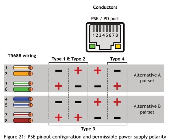
    I'd like to ask about permissible power supply polarity of PSE pinout. Both of Alternative A and B pairsets are defined and the type4 PSE is only permitted to use one polarity configuration.

    I am wondering why the Type4 PSE must use the specific polarity configuration? Is there any spacial purpose? 

    PDs for any type is required to support any polarity configuration, which means it is a must that have rectification is needed in the PD. So what's the purpose of define polarity configuration? The polarity will be fixed after the rectification, isn't it? If the polarity will be fixed after the rectification, then the polarity is not that important from my point of view.

    Please advise, thank you very much!

  • Hi Steven,

    Talking with our IEEE committee members, there was no special reason for this. Thanks!

  • Hi Darwin,

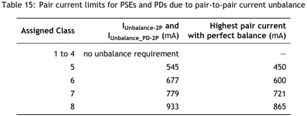
    Below the Current Unbalance is defined in 802.3bt spec, I wonder what kind of action the PSE would take if one pair current of the pairset is over the limit? Just cut off the power or force the pair-to-pair current to perfact balance as possible and keep powering? 

    What's the purpose of defining Current Unbalance in 802.3bt spec?

    Thank you!

  • The purpose of current unbalance spec is to make sure the PoE system does NOT overheat under 4-pair operation due to a high amount current flowing through 2 of the pairs because the PoE system was designed with higher effective resistance on the other pairs. In this case, you do NOT want the PoE system to remain operational.

    The PSE will check each channel separately and if the current exceeds the power that was allocated to the PD, the PSE will foldback that channel. This way each pair set is always protected.