This thread has been locked.

If you have a related question, please click the "Ask a related question" button in the top right corner. The newly created question will be automatically linked to this question.

LM25118: The Charge inductor getting hotter along with loading &time increase

Part Number: LM25118
Other Parts Discussed in Thread: LM5118

Hi Ti Team:

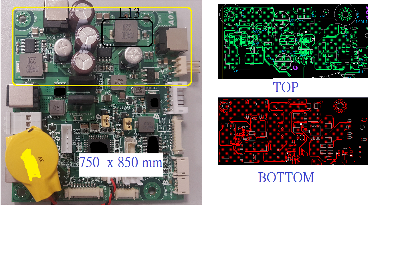
After I use the LM25118 now has a problem..SRPG1207-6R8M-AW.pdf

The Charge inductor getting hotter along with loading &time increase for a short time-then IC no output

My spec is:

One input and use two LM25118 ic for Output,

Vin= +12v to +24v

Vout = +12v to +19v

Iout = 6A

Below is the related schematic:

I had tried adjust inductor, Vout, Comp ; the result is all the same

If you have any recommend please let me know

Thanks!!

pw-mcu-01_191126_rename.pdf

  • Hi Su,

    Thank you for considering the LM5118.  I am confused by the inductor LB4.   While I am forwarding this to our expert, can you explain why you placed an inductor there?  Which one is referred to as the Charge Inductor, the LB4 or L13?

    Thanks,

    Youhao

  • Hi Youhao:

    Thanks for your reply,

    The Charge inductor is L13, LB4 is for protect the initial power(VIN_12-24V_protect)while high side Mos work,

    Now I remove it and the square wave is normal ,but L13 fast hot condition still exist;

    I think the PCB size may effect but I don't know why L13 hot so fast

    (ex:3A loading the L13 temperature raise to 100C during 3 sec,then you can hear the rapid switching sound by inductor or Mos  then shut down)

    Thanks!!

  • Hi Su Roger,

    I recommend removing LB4 and shorting it out. The drain of QB9 should be a stable voltage. Typically it is connected to a capacitor.

    I have a few questions.

    1. What is the value of L13?

    - I see in the datasheet you provided the value is 6.8uH but the schematic indicates 22uH

    - If using the 22uH what is the rated saturation current?

    2. What is the value of RB5?

    3. Please probe the UVLO pin to see if it is getting pulled low and then re-charging. This will indicate an over current condition. 

    4. If you decrease the load, (~500mA) is the issue still there?

    Thanks,

    Garrett

  • Hi Garrett Roecker:

    Thanks for your help,below is my reply:

    1. What is the value of L13?

    - I see in the datasheet you provided the value is 6.8uH but the schematic indicates 22uH

    - If using the 22uH what is the rated saturation current?

    ==>22uH was used at the beginning , after the issue be found I tried to use  6.8uH ,the WEBENCH suggest

    but the issue  still have, below is 22uH datasheet,Isat=5.5A0001_SRPN1004-220M-S.pdf

    2. What is the value of RB5?
    ==>0.01 OHM,1W,12060002_TRLM-12XX001E(5~30 歐姆).pdf

    3. Please probe the UVLO pin to see if it is getting pulled low and then re-charging. This will indicate an over current condition.
    =>The UVLO pin voltage level is always at 1.3v, even at the begging also 1.3v

    4. If you decrease the load, (~500mA) is the issue still there
    =>Yes, still have,
    but the temperature raise not so fast, so it may average to the room temperature,

    maybe few hours later has the same overheat condition

    Thanks!!

  • Hi Su Roger,

    The 6.8uH inductor is only rated for a saturation current of 16.5A. Worst case for your design the inductor current can be higher than this  I recommend charging to an inductor with a saturation current greater than 22A. Based on the current levels you are using now it seems there is not a lot of copper to sink the heat from the inductor. Can you send me a picture of the board?

    Can you please send me copy of the schematic with the capacitor values? There are some values that I want to check but the part numbers are not showing up online.

    Thanks,

    Garrett

  • Hi Garrett Roecker:

    ok,I will try to use 6.8uH, Isat=38A on next version;Now I have no sample to test

    below is the  information related to the board:

    And please reference to the attached Excel file, You can find the value by component location,LM25118 capacitor spec.xls

    Thanks!!

  • Hi Su,

    Thank you for the pictures but we cannot easily locate the parts or trace the signals.  Anyway, please change the inductor as Garrett recommended, and let us know if you see improvements.

    Thanks,

    Youhao