This thread has been locked.
If you have a related question, please click the "Ask a related question" button in the top right corner. The newly created question will be automatically linked to this question.
Hello,
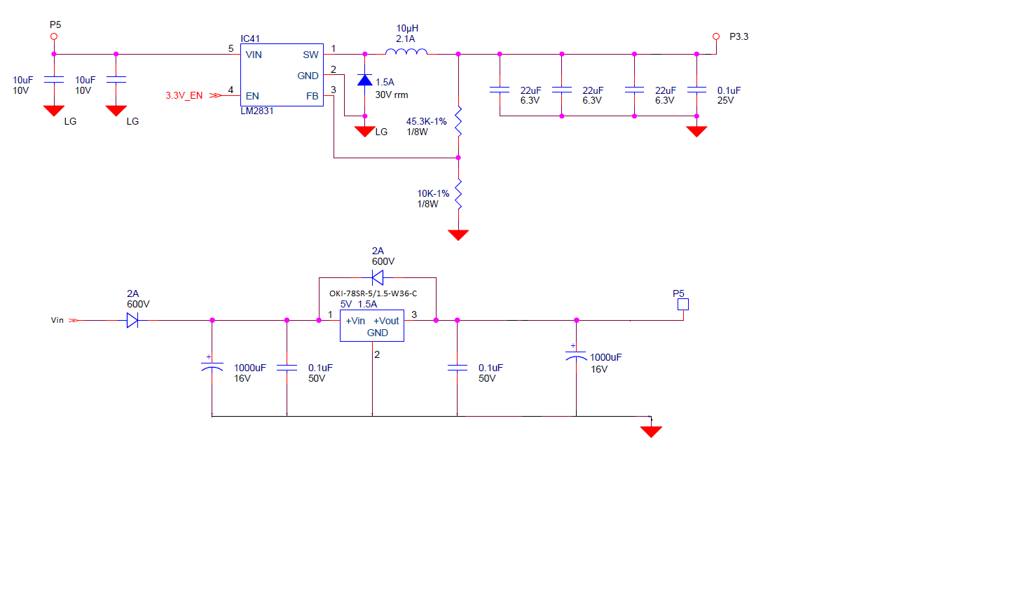
We have been having FPGA I/Os go bad and we think it might be caused by the 3.3V LM2831 regulator supplying power to it. The maximum FPGA's maximum allowed I/O power supply voltage is 3.6V.
After power is initially applied, the output of an LM2831 goes up to 3.860V (as shown in the image below, Nominal voltage is 3.3V). The input is fed by the 5V output of another LM2831.
What can we do to reduce the voltage overshoot?
Thanks,
Stephen
I am using an LM2831 to generate 3.3V. The input of the LM2831 is supplied by 5V from the output of another LM2831.
Hi Stephen,
Could you please provide a schematic of the system. Also, could you please specify the input voltage of the first LM2831 and maximum load being used in both devices.
Regards,
Febin
Hello Febin,
The regulator used for P5 is not an LM2831. It is a OKI-785R-5/1.5-W36-C.
Below are the P3.3 regulator's Loaded startup voltage and current. and No-Load startup Voltage (P3.3 disconnected from rest of circuit)
The person performing the test used a five turn conductor to measure the current, so divide the current by 5 to get the actual value. As shown below, the current went up to about 2 Amps. The steady state current is around 151mA.
Stephen
P3.3 Loaded Startup Current (blue) and Voltage (Pink):
P3.3 No-Load Startup Voltage:
Hi Stephen,
Thank you for the details. Please provide the complete part number of the device.
Regards,
Febin
Hi Stephen,
Unfortunately this is a very old part. We do not have a drop-in replacement for LM2831XMF/NOPB.
But we have some really good new devices like TLV62565/6 or TPS6282x. But the customer shall be responsible to carefully check the device & test it for its suitability in your complete application. Please let me know if you need any further assistance.
Regards,
Febin
Hi Stephen,
Could you please give the Iout used. I assume Vin is 5V and Vout is 3.3V
Regards,
Febin
On the schematic I previously posted, Vin was 8 to 10V AC and that supplied a OKI-7858-5/1.5-W36-C regulator. The output of that
regulator supplied 5V to the LM2831 and the LM2831 was configured to output 3.3V.
The LM2831's nominal output current is 151mA. At startup, it jumped to almost 2A (see image in previous post).
Hi Stephen,
Please be informed that I am discussing with my team regarding this. Unfortunately, I do not have the EVM and could not take the measurements for the device. I will get back to you early next week.
Thank you for your understanding!
Regards,
Febin
Hi Stephen,
After a careful analysis, I think the problem is with the filter design.
1. Referring to equation (7) in the datasheet, substituting values I get an inductance of 1.2 µH with 20% inductor ripple current. Please consider Iout as 1.5A as the design is based on the maximum output current of LM2831. Vin is 5V and Vout is 3.3V for LM2831 as per the schematic.
(You may have considered Iout to be 151mA and hence arrived at a higher inductance value as seen from the schematic)
2. Secondly, the output capacitor is one of the two external components that control the stability of the regulator control loop, most applications will require a minimum of 22 µF of output capacitance. As seen from the Design Example 3 in the datasheet, the output capacitance can go upto 2 x 22 µF if necessary.
3. Inrush current at start-up will depend on the output capacitor selection.
4. By reducing the filter size, the control loop will get faster and the voltage overshoot will also decrease.
5. In any case, we recommend you to use our newer faster devices like TPS62825x for better performance.
Please use the recommended values for inductor and capacitors and test the application again. Please let me know your feedback.
Regards,
Febin
Hi Stephen,
I would like to follow up on this. Do you have some updates?
Regards,
Febin
Hi Stephen,
The problem seems to be with the filter design and this is applicable even if you choose LMR10515.
Regards,
Febin
Hi Stephen,
Could you change the filter design or try with a newer device?
If you have the same problem with our newer device or if you may require any assistance on the alternate device suggested please open a new request.
Would you then be okay to close this post now?
Regards,
Febin
We found out what was causing the original issue that caused me to post this question, i.e. I thought the high voltage overshoot was damaging a device, but it was not.
I don't have time to look into this issue right now, so I think you can close this thread.