This thread has been locked.

If you have a related question, please click the "Ask a related question" button in the top right corner. The newly created question will be automatically linked to this question.

TPS63000: Device drains 160mA from the source with no load at the output.

Part Number: TPS63000

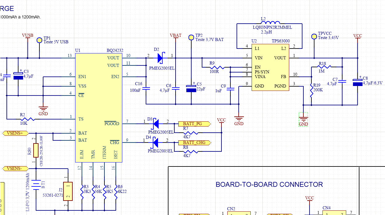
We are using the TPS63000 to regulate the circuit supply voltage around 3.45V as shown in the image below:
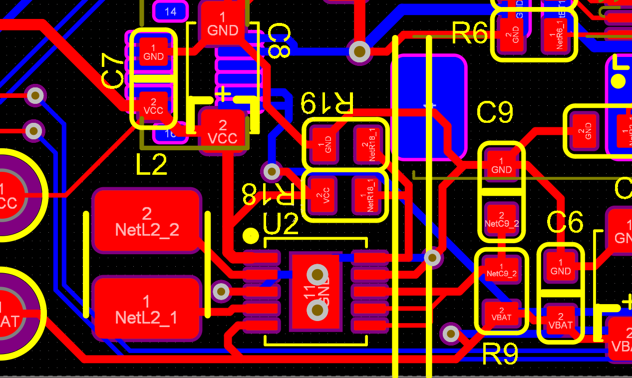
PCB layout:

The supply voltage comes from a 3.7V LIPO battery or a 5.0V USB port.

The circuit was designed following the guidelines of the datasheet (SLVS520C –MARCH 2006 – REVISED OCTOBER 2015).

When feeding the circuit with 2.6V, even with no load at the output, the TPS6300 drains 160mA and heats up. Above that tension, it heats up so much that it ends up disarming.

The output voltage is stable at 3.58V for input voltage from 2.0V to 2.9V. When the input voltage exceeds this range, the output voltage starts to rise and the TPS heats up even more.

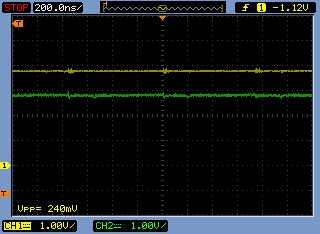
INPUT=GREEN(2,8V) OUTPUT=YELLOW(3,6V)
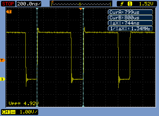
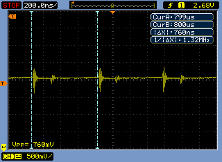
INDUCTOR FREQUENCY.

INPUT RIPPLE DUE TO TPS63000 CYCLE.

  • Dear Cicero,

    thank you for using our device and for sharing all this information right away.

    Looking at your schematic your choice of caps is not optimal.

    According to the application guidelines here , please consider the following changes:

    C6: increase to min 10uF ceramic (you can keep the electrolyte C5)

    C9: reduce to 0.1uF, this is a filter cap

    C7: increase to 10uF ceramic

    C8: exchange with ceramic and increase to 10uF

    this is necessary for the basic stability.

    In your layout I see a couple of items, which are not optimal, please see here for recommendations

    - Your GND connection doesn't have a plain

    - Both input and output caps are too far away from the device. This can cause instability.

    In scope plot 2 (Inductor frequency), can you please let me know, which pin you measured, L1 or L2.

    regards,

    Moritz

  • Hi Cicero,

    hope your problems were solved.

    regards,

    Moritz