This thread has been locked.

If you have a related question, please click the "Ask a related question" button in the top right corner. The newly created question will be automatically linked to this question.

TPS23754: PoE PD cannot output 12V.

Part Number: TPS23754
Other Parts Discussed in Thread: CSD19534Q5A, PMP9563

Hi Sir,

We found PoE failure issue on a few samples.Our preliminary analysis is high-side MOSFET(Q803) of secondary side short to GND. After we replaced new MOSFET ,PoE can output normally.

This failure phenomenon occur when PoE injector plug in/out DUT rapidly or repetitively.

Do you know why MOSFET short to GND?  How to resolve this issue?

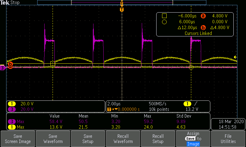
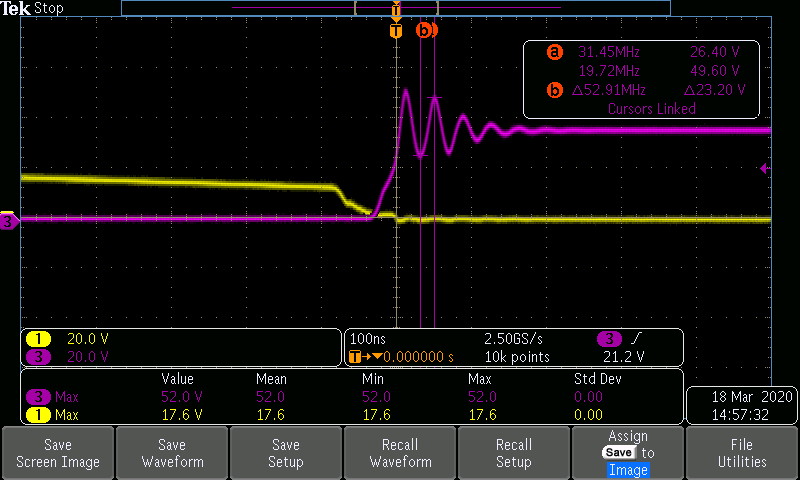
Attached the failure waveform and our PoE schematic file.

 .

DL5P1_EVT_PoE_circuit.pdf   

  • Hello Chen Jianjhong,

    It could be that the FET is breaking due to voltage spikes during shutdown. You could  measure VDS of the series FET during these shutdowns to capture the peak voltage. If this is the case, this can be solved with either higher rated FETs or placing DCR and RC snubbers across the series FET (Q803).

    If this post answers your question, please indicate so by marking this thread as resolved. Thank you.


    Regards, 


    Michael P.

    Applications Engineer

    Texas Instruments 

  • Hi Michael,

    Thank you for your response. 

    I see TI reference design(PMP9563 REV A) and it also use the same FET(CSD19534Q5A) and  FET VDS rated voltage was 100V ,but this reference design has no any DCR or RC snubber circuit reservation.

    So ,did you see the same FET issue on your EVB or other customers before?

    Do you mean "shutdown" is injector plug out ,or FET turn off?

    In addition ,whether primary side dead time increasing can avoid voltage spike on FET during shutdown ,or not?   

  • Hi Michael,

    The following picture is secondary side Vgs waveform ,it shows one step on ch3 ,is this step normal?

    Thanks.

  • Hi Michael,

    This picture is insert injector action ,voltage spike of VDS is about 58V ,it should be less than FET spec.

    I know to add DCR or RC snubbers can improve voltage spike ,but this spike should not cause FET shoot through.  

    Whether this DC converter forward architecture exist FET shoot through risk when PoE injector plug in/out DUT rapidly or repetitively ,or not? 

    Picture 2:

    In general ,this voltage spike(ringing) cause radiation noise emission easily ,is it right? 

    Thanks.

  • Hello,

    changing the dead time will marginally change the voltage spike. 
    This spike is on the drain -source during power down. If the spike is on the FET margin, then plugging power in and out rapidly will expose this. 

    I suggest measuring VDS during shutdown. Then we can decide if this is the problem. 

    If this post answers your question, please indicate so by marking this thread as resolved. Thank you.


    Regards, 


    Michael P.

    Applications Engineer

    Texas Instruments 

  • Hi Michael,

    The Vds during shut down waveform picture as below ,this spike is very higher on Q803 ,I think we should need to add snubbers on Vds(Q803) to improve this spike.

    Can you help calculate snubbers R/C value?

    Thanks.  

  • Hello,

    Choosing the 'right' values for snubbers can be challenging. The basic practice is to choose a snubber that will be equivalent to the characteristic impedance of the resonant circuit. Usually that will give a good place to start (if you can calculate it), but with parasitics and component tolerances, it will have to be adjusted.  

    I find it easier to go with what has worked in the past for similar designs, and then adjust as needed. In a 12V ACF, I have seen 5ohm for the resistor and 1nF cap. 

    Additionally, a DRC snubber could be put in parallel with the RC snubber to further dampen the signal if needed. 

    If this post answers your question, please indicate so by marking this thread as resolved. Thank you.


    Regards, 


    Michael P.

    Applications Engineer

    Texas Instruments