This thread has been locked.

If you have a related question, please click the "Ask a related question" button in the top right corner. The newly created question will be automatically linked to this question.

TPS61022: Boost convert inrush current and single cell removable lipo battery protection

Part Number: TPS61022
Other Parts Discussed in Thread: LMC555,

Hello, quick question.

I am in the process of implementing a single cell lipo (LiHV 3.8v) cell protection, mainly from undervoltage.

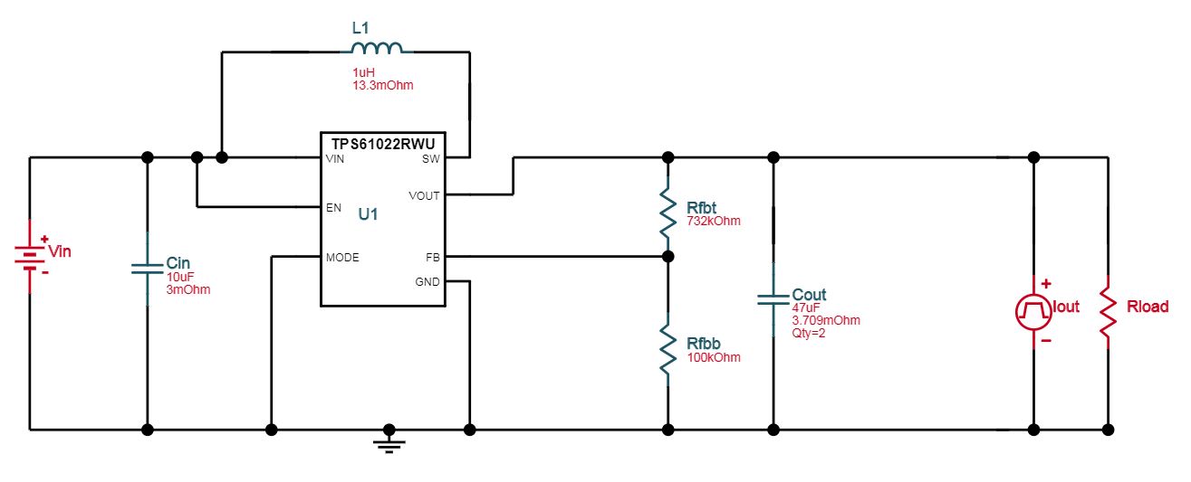
I am using a cricut design generated from webench which works well for my application (3.8v to 5v 2.5A).

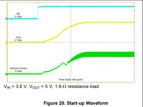
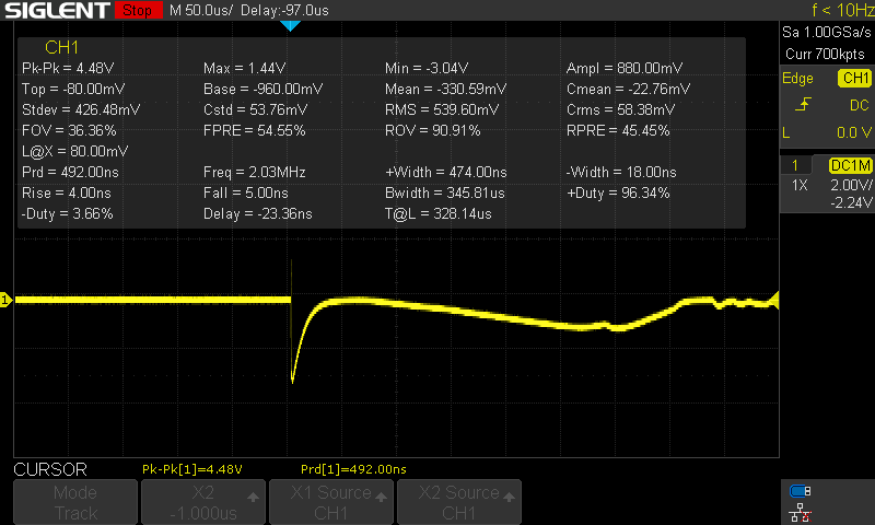
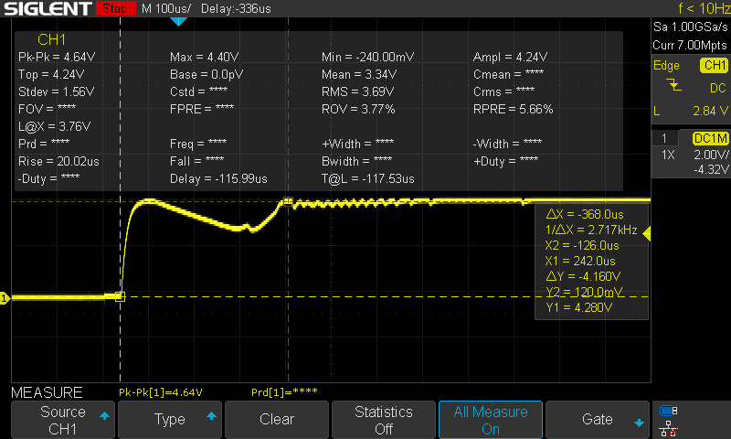
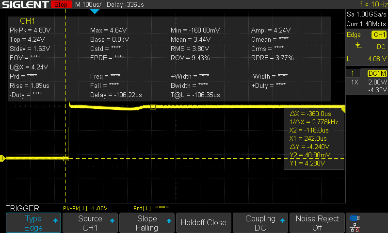
While trying to implement a protection circuit, I ran into a problem with inrush current at startup. It probably pulls about 8 or so amps on start up very briefly which the lipo can accept but any lipo protection circuit kicks in. So my first battle is solve the issue of the large inrush. See boost design below.

My OC protection would be probably around 3 amps or so. Is that possible to obtain on startup ?

The coil is a 994-XAL7030-102MEC.

Note from the screen shot there are actually 2 10uf input caps and 3 22uf output caps use in my design form previous generated design.

Second lesser question, is there an alternative single cell protection chip without the need to pulling up the output when a new battery is plugged into the input? without charger, and/or is there another enable the output? I was thinking of a lmc555 timer in a one shot, but that looks to have issues of its own, as its cmos logic.

I might end up using a dw01b or similar chip which seems to work without needing to pull up the output fet.

  • Hi Vismantas,

    The 3 Amperes overcurrent protection is not big enough for your application. Considering the input lipo cell minimum voltage 3.0V and output power 5V*3A=15W. The calculated maximum input average current would be 15W/3.0/0.9=5.55A. 

    Below is the startup waveform of TPS61022EVM. TPS61022 has soft-start function so normally there will be no big inrush current. Can you share the inrush current waveform on your board?

    For the second question, I'm not familiar with single cell protection chip products. Please post a new thread dedicated for this. 

  • Hi Zach,

    Thanks for your input,

    Here is waveform I am getting when I plug in a single cell lipo, I used 3x 1.5 ohm 3/4w 1%  in parallel for a quick test,(0.333 Ohm), and after a little ohms law I got almost 10A (9.85A) on the input (about 4 - 4.3v LiHV lipo battery). Do these figure seem normal?

    Here is a few screen shot of the inrush current on the input when a battery in plugged in:

    As well for interest:

    Here is the input waveform when I plugged the battery in from the 0.333 ohm resistor in line when I measured the current: slight voltage sag, but If I measure directly without the shunt resistor I get no voltage drop

      .

  • Hi Vis,

    I'm totally confused of how you run the inrush current test. 1) 3 * 1.5ohm resistor in parallel, the resistance would be 1.5ohm/3=0.5ohm, not 0.333ohm. Please double check this value. 2) If I understand correctly, the first four waveform is captured when the 0.5ohm (or 0.333 ohm like you said) shunt resistor in series between the battery and TPS61022 boost converter input, correct? 3) What's the meaning of the last two picture? How did you test? 4) As I calculated in previous post, the steady state average input current would be 5.5A if the Li battery voltage drops to 3.0V. So the 3A battery OC protection spec is not high enough.
  • Hi Zack,

    Yes sorry you are totally right it is 0.5 ohm.. not sure how I missed that, wrong values. even so, yes at 3v it would be close to 6A which matches your waveform, and fully charged at 4.35v It would be about 8.7A? non the less I can see why the the protection IC would kick in, I have new higher rated mosfets coming in tomorrow for experiment, should solve my issue.

    Yes you are correct the resistor was in between Battery + and input vcc +.

    I did the test by simply plugging in the lipo battery in the board, after waiting about 15-30 second beforehand to discharge any charge left in the capacitors (worse case when swapping batteries).

    Thank you.

  • Hi Vis,

    At 3V battery voltage, input current is 5V*2.5A/0.9/3.0V=4.6A. At 4.35V battery voltage, input current is 5V*2.5A/0.9/4.35=2.6A. So protection IC would be at least 5A. Considering the load transient and TPS61022 switch current limit 8.5A spec, a higher current rating (>8.5A) mosfet would be recommended.

    When you did this test by simply plugging in the lipo battery in the board, you should consider there are a lot of input capacitors on the board, not only TPS61022 input capacitors. This input capacitors need to be charged to the battery voltage in a very short time. This has no relevance with TPS61022. Besides that, if the input caps instant charging current is 6A, the voltage drop on 0.5ohm resistor is 6A*0.5ohm=3.0V. I would recommend you use a current probe to test the input inrush current. Or use a much lower resistance (0.05ohm) not to have effect on the normal working.

  • Zack,

    Thanks for your help, I ended up using Omega AON2406 mosfets as a replacement, according to there datasheet the RDSon and VGS matched my application, and in testing it proved to be functional for my application.

    Thanks again.