This thread has been locked.

If you have a related question, please click the "Ask a related question" button in the top right corner. The newly created question will be automatically linked to this question.

TPS40210: TPS40210 maximum duty cycle

Part Number: TPS40210
Other Parts Discussed in Thread: LM5155, LM5022, PMP20676

Hi Richard,

I used the Power Stage designer with parameters flaybak transformer 20 uH / 7,5:1 / 100kHz and got the following results:

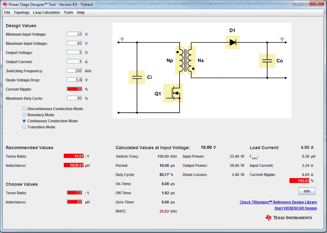
My question is: Is it possible to design TPS40210 in this duty cycle?

Thanks,

Tsvetan

  • Hi Tsvetan,

    TPS40210 datasheet has specifications for minimum on and off-time, where on-time is defined as duty cycle*period, and off-time is (1-duty cycle)*period. 

    At 100KHz, your specification is fine, but your inductance is much too high. This can reduce your power density and efficiency because your inductor would be incredibly large. I would recommend finding another transformer that has a higher turns ratio that allow for more flexibility. 

    Additionally, there is also the next-gen version of the TPS40210, which is the LM5155. 

    Looking back at your original post, I found a suitable reference design that you can use that follows the LM5155 for a non-isolated output, and an isolated output. Please take a look and let me know about what you think. 

    http://www.ti.com/tool/PMP22170

    There is a design guide for the LM5155 Flyback if you would like to go this way: 

    http://www.ti.com/lit/an/snva866/snva866.pdf

    Thanks,

    Richard

  • Hi Richard,

    Design is entering its final phase, but I have some concerns. The flyback transformer (EPCOS B82802A0055A225) is designed for 36-60 volts, and I use it for an input voltage of 10 to 60 volts. With a turns ratio 7.5: 2.5: 1 and a duty cycle 0.91, will I be able to get output voltages of 5 and 12 volts DC? Everything is fine by design calculations(DesignValues_12V_LM5022.jpg), but still, please check the design for major bugs.

    Thanks,

    TsvetanPower Board 1.0.zip

  • Hi Tsvetan,

    Sorry for the delayed response. I would first recommend to make sure your transformer rating is fit for your input voltage. Addtionally, you should make sure that you do not violate the minimum on and off-time of the IC. I will take a closer look at your design files, and give you my feedback by next week.

    Thanks,

    Richard

  • Hi Richard,

    I am sending you my final design with the LM5022. I would be grateful if you would look into it. I have doubts about the values and configuration of the compensation components. I'm currently designing his circuit board and use PMP20676 and TIDA-01134 as examples.

    Thanks,

    TsvetanFlyback_LM5022.zip

  • Hi Tsvetan,

    Thank you for the files. I will take a look at it and give you my feedback my Tuesday.

    Thank you,

    Richard

  • Hi Tsvetan,

    Sorry for the delay. 

    In general, your power-stage design looks fine. 

    Your configuration of the compensation network is correct. The error amplifier should be disabled, since you are controlling COMP externally. 

    I would change Ccomp to 1.5nF, since C_comp should be equal to 1/(w_zea*R_fbt). .

    Thanks,

    Richard


  • Hi Richard,

    Thank you very much for your efforts with this project. I will change the value of the capacitor you specify. I will try to send you the test results of this design.

    Best regards,

    Tsvetan