This thread has been locked.

If you have a related question, please click the "Ask a related question" button in the top right corner. The newly created question will be automatically linked to this question.

TPS92515: About OFF-Timer, Shunt FET Dimming or Shunted Output Condition

Part Number: TPS92515

Hi,

Following circuit example is introduced in the data sheet.
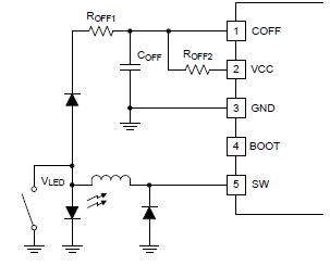
Please tell me about Shunt FET Dimming circuit.

1.Can this circuit configuration be realized unless the VLED voltage is higher than "VCC voltage + Vf"?

2.In this circuit configuration, VCC sinks current when the Shunt FET is off.
   In that case, Customer wants to know the maximum current value that the VCC can sink.


Best regards,
Yusuke

  • Hello Yusuke,

    1) Yes it can work with Vled + Vf being lower than VCC.  The off-time just needs to be calculated with both currents supplying Coff.  The current from VCC should be much less than the current from Roff if designed appropriately.  This can be done different such as moving the diode to the VCC side and connecting Roff directly to Vled.  The calculation is just different.

    2) In the EC table under VCC/reference regulator:  "IVCC(ILIM) VCC regulator current limit VCC shorted to GND 14 19 23 mA", the minimum is 14 mA which is much more than will be needed.  Note that at high input voltage the overhead is dissipated in the IC.  At 55V input every mA drawn from VCC will cause 50 mW of dissipation in the TPS92515 since it is basically a linear regulator.

    Best Regards,

  • Hi Irwin,

    Thank you for you kind support.
    Could you explain to me in a little more detail please?

    >1) Yes it can work with Vled + Vf being lower than VCC.  The off-time just needs to be calculated with both currents supplying Coff. 

    I am confused by your answer.
    In this example circuit, VLED needs to be higher than VCC + Vf.
    Is this understanding right?

    >2) In the EC table under VCC/reference regulator:  "IVCC(ILIM) VCC regulator current limit VCC shorted to GND 14 19 23 mA", the minimum is 14 mA which is much more than will be needed. 
    >Note that at high input voltage the overhead is dissipated in the IC.

    I asked about the current flowing into VCC.
     "IVCC(ILIM) VCC regulator current limit VCC shorted to GND 14 19 23 mA"

    The above current value is recognized as source current.
    Is there a regulation for sink current?

    Best regards,
    Yusuke
  • Hello Yusuke,

    1)  No, it doesn't have to be higher.  The off pin operates from 0V to 1V.  Roff, or Roff + Roff2, or just Roff2 when shunted, charges Coff.  Once the off pin hits 1.0V the pin is pulled to zero volts.  This is the point the TPS92515 turns on the MOSFET.  The off pin stays low until the CS pin hits peak current threshold.  At this point the MOSFET turns off and the off pin stops sinking current allowing Roff, or Roff + Roff2, or just Roff2 when shunted, to charge Coff.  If Vled is higher than VCC then the only current flowing to Coff is from the original Roff.  in the shunted case the only current charging Coff is Roff2.  In the case where Vled is lower than VCC + Vf then both Roff and Roff2 charge Coff, two current sources into Coff.

    2)  I don't understand this question, the current does not source into VCC, the current is sourced from VCC.  The above current from Roff is a source current that sources into the off-pin.  This pin operates from 0V to 1V.  If there is an additional Roff2, it will source current into the off-pin as well from VCC.

    Best Regards,