Hi Expert,
Customer use TPS24741 to ORing and hotswap between two 12V rails. The system voltage 12V is working fine(won't reboot) when switch from main to aux. However, when switch from aux to main, Vsys will reboot. Would you please provide some suggestions how to translate smoothly without system voltage drop? Thanks.
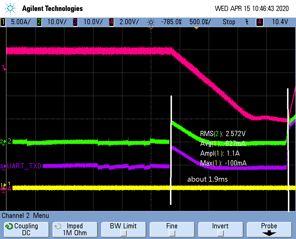
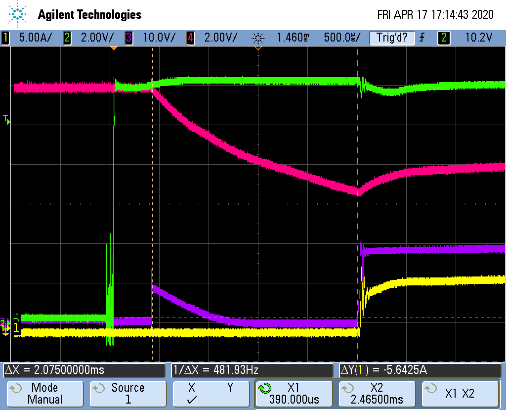
Yellow: system voltage12V
Green: 12Vaux
Red: 12Vmain
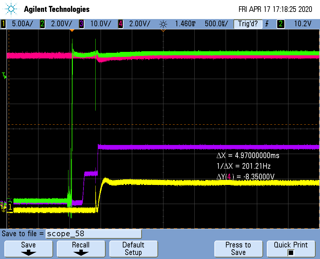
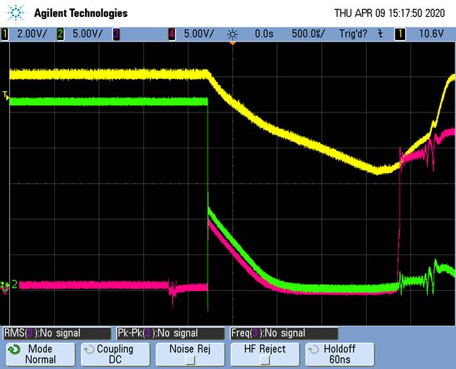
Yellow: system voltage12V
Green: Vgateaux (U60 pin4 in the schematic)
Red: Vgatemain (U63 pin4 in the schematic)
Allan