This thread has been locked.

If you have a related question, please click the "Ask a related question" button in the top right corner. The newly created question will be automatically linked to this question.

BQ2970: Battery Protection IC BQ29707 don't work

Part Number: BQ2970

Hi everyone,

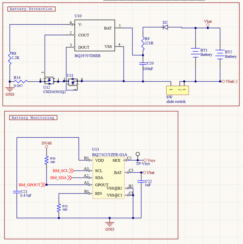
I've designed a PCB and now I am in the process of testing. I have combined the battery protection IC BQ29707 with the battery fuel gauge BQ27421 and a wireless charging IC BQ51050.

My problem is that when I connect the Li-Ion battery I get strange behavior... I measure around 1V at the output (actually it is fluctuating 1.0 - 1.1 volts)... As soon as I turn on the wireless charging then I am able to measure the correct voltage around 4.2 - 4.1 volts. Even after I disconnect the wireless charging, I keep measuring the correct voltage. When I disconnect the battery and connected back I have the same problem..

It is very strange, it is like the MOSFETs (U11 & U12) turns on as soon as I connect the wireless charging...

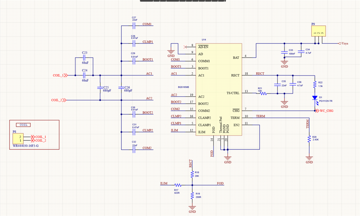
These are the schematics for battery protection, battery fuel gauge, and wireless charging. I believe that the problem somehow lies in battery protection but I cannot figure out what is going on. Also, I place a diode (D2) for reverse polarity protection which I have removed now to avoid the voltage drop. It is like the Mosfets turn on only when I connect the wireless charging but I do not know how this is related.

Any suggestion?

  • Hi Nikos,

    There is a note in the BQ2970 datasheet that might be related to what you are observing: 

    "When the battery is connected for the first time, the discharging circuit might not be enabled. In this case, short the V– pin to the VSS pin. Alternatively, connect the charger between the Pack+ and Pack– terminals in the system."

    Regards,

    Matt

  • Hi Matt,

    Thanks for your prompt response. Ok, when I short V- pin to the VSS pin the MOSFETs turn on and I can measure the correct battery level (4.06V). When I disconnect and then reconnect the battery I have again the same issue and I need to short again V- pin to the VSS pin... Why does this happen? Any suggestion?

  • Hi Nikos,

    I think in most applications the protection IC is in the battery pack and is always connected to the battery. In this case, the user only needs to short V- to VSS one time when the pack is first assembled.

    Recently, this other user was facing the same challenge where they wanted to automatically turn on the FET when they insert a new battery cell. They came up with a couple of possible solutions: https://e2e.ti.com/support/power-management/f/196/t/889180

    Best regards,

    Matt

  • Thank you for your assistance Matt, now the problem is clear to me.

    However, I still do not understand why by connecting the charger to PACK+ and PACK-  DOUT is enabling... Could you give me a simple explanation?

    Nick

  • Hi Nikos,

    When there is a fault that turns off DOUT (battery is over-discharged), the protector IC turns off the DSG FET to prevent further discharge of the battery and the V- pin is internally pulled up to BAT in order to put the device in standby mode to reduce the current consumption even further. You can view the connection of the battery as coming out of an over-discharge situation. For the device to come out of standby mode, the voltage difference between V- and BAT needs to be greater than 1.3V.

    Regards,

    Matt