This thread has been locked.

If you have a related question, please click the "Ask a related question" button in the top right corner. The newly created question will be automatically linked to this question.

LM3017: Boost converter with True Shutdown used as High Side Switch

Part Number: LM3017

Hi,

Can LM3017 be used as a high side switch with True Shutdown? In our application, we really need to minimise shutdown current and keep it in the nanoamp range.

My thoughts are as follows.

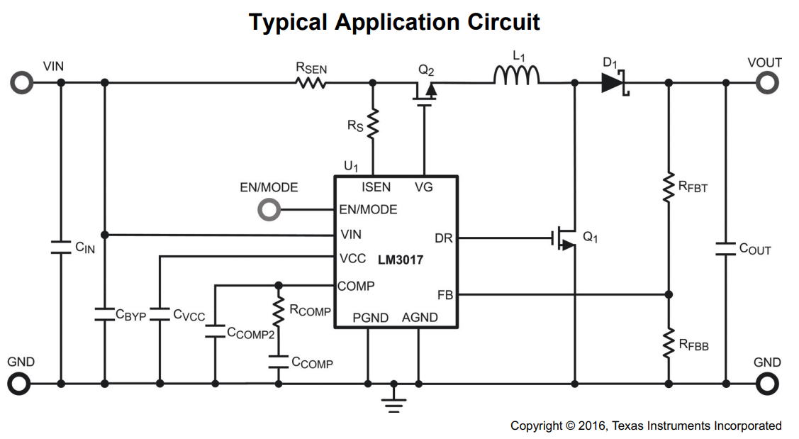
  • Remove L1 and D1 (from the typical application circuit).
  • Keep Enable ≤ 0.4V for shutdown mode.
  • Keep Enable ≥ 2.6 V for passthrough mode.

But

  • What should we do with the Feedback pin?
  • How can we disable current limiting so that this high side switch can work with a high current power FET (N-channel) ? Or can we trick it into never seeing overcurrent?
  • Will any of the above have a negative effect on shutdown and operating/quiescent current?

The 40nA shutdown current is far too good to pass up. However, the 1µA maximum is enough to rule it out.
Can you please tell me what factors could cause LM3017 to go from 40nA to 1µA in shutdown so that we can evaluate where it would mostly sit?

Please know that I'm still going to continue my other thread about high side switches because something better may still come from it. If I'm wrong about how LM3017 works then I don't want to derail that thread since I still need help. https://e2e.ti.com/support/power-management/f/196/t/895959

  • Hi Dan,

    what is the voltage range the VIN? could you just use a P-MOSFET instead of the LM3017?

  • Hi Jasper,

    V(in) = V(out) = between 9V-14V

    V(logic/enable) = 3.3V

    We have a 100A N-channel MOSFET in the BOM so we were hoping to use that with LM3017 as the gate driver. Either way, the problem is with the shutdown current of actual gate drivers.

    Below 500nA is ideal and above 1μA is too much.

    The LM3017 boost converter has a typical shutdown current of 40nA. Although, the confusing part is that the characteristics table says it's 25nA.

    As for operating current, we are considering up to 1mA. Or 10mA as a last resort. Microamps would be better.

    Kind regards,

  • Hi Dan,

    I could use the EVM to run a bench test to see if this device works as a load switch controller. It may take some days because I'm applying the EVM from ti store.

    Meanwhile, I can ask somebody why the shutdown current maximum spec is up to 1uA.

  • Hi Zack,

    Both of those things would be incredibly helpful. Thank you so much!

    Kind regards,

  • Hi Dan,

    Just receive the EVM today and test it quickly by removing inductor L, diode, feedback resistors, comp pin resistor and capacitors, looks like this device could work as a high side switch controller. 

    I'll run more test to see the over current protection function tomorrow. Detailed report will share to you later.

  • Hi Zack,

    Thank you. That is great news. We really appreciate your efforts and can't wait to see the report.

    Do you think using the LM3017 as a high side switch will compromise it's shutdown or operating quiescent current in any way?

    Kind regards,

  • Hi Zack,

    Since Q1, RFBT and RFBB are used for overvoltage protection when in Boost mode, is it possible to also remove them?

    If we're using the LM3017 as a high side switch, it doesn't seem like we would ever need Boost mode.

    Kind regards,

  • Hi Dan,

    Using the LM3017 won't compromise the shutdown current. Reason is no matter the inductor L, Q1, D, Cout, Rfbt, Rfbb, Compensation are removed or not, when EN/MODE pin is less than 0.4V, the internal circuits are shutdown and drawing the same current. The quiescent current will also be the same.

    Yes, I removed the Q1, RFBT, RFBB on EVM, it won't affect the current sense function. 

    How would you control EN/MODE pin? If you use a 3.3V GPIO to enable or disable, then LM3017 works at pass-through mode. The VLIM1 spec is 85mV. So you have to use a very small current sense resistor.

    So far I didn't see any errors on bench by using it as a high side switch. 

  • Thanks Zack,

    It's as you say. We'll be controlling EN/MODE with a 3.3V GPIO.

    We already have a 2mΩ sense resistor in the BOM. Will that be enough?

    Although, we already have current limiting closer to the battery. I was hoping to disable sensing in the LM3017, or at least set it to a much higher value which we can work with.

    Kind regards,

  • Hi Dan,

    The 3.3V for EN/MODE will set the device work at pass-through mode. The minimum VLIM1 spec is 70mV so the minimum current limit is 70mV/2mohm=35A.

  • Thanks Zack,

    Can we increase the current limit with a smaller sense resistor? e.g. 1mohm = 70A ?

    It seems like that's what you were saying but I wanted to make sure I haven't misinterpreted.

    Or, can we short ISEN to VIN to disable current limiting? e.g. remove Rs and Rsen.

    Kind regards,

  • Hi Dan,

    Yes. You could do that since you already has a current limiting close to the battery.

  • Thanks Zack,

    You were very helpful.

    Kind regards,