This thread has been locked.

If you have a related question, please click the "Ask a related question" button in the top right corner. The newly created question will be automatically linked to this question.

ISO5852S: Global shutdown with fault output.

Part Number: ISO5852S

Dear sir,

We are using ISO5852S for our 3 leg inverter. To achieve the global shutdown, we connected the IN+ terminal to FLT terminal. But it reduces the FLT output terminal voltage during the normal operation. we posted the query at https://e2e.ti.com/support/power-management/f/196/t/890991

As per the suggestion, we connect the IN+ directly to  VCC and tested the PCB. When desaturation fault is detected in any one of the six driver, the fault output goes low and works well. During normal operation condition the FLT output shows 5.1V. 

But if the fault occurs at any one of the driver, only the specified driver output goes low and all other gate driver outputs are working continuously. 

If we connect the IN+ to the FLT terminal, the global shutdown option works well. If desaturation fault occurs in any one of the driver, it disable all the switches. But during normal operation the FLT output was dropped to 3.328V.

We wish to use the global shutdown option and FLT output LED indication. Could you please suggest the suitable solution for the same. 

Thanking you. 

Thanks & regards,

Rajasekaran. 

  • Hi Rajasekran,

    Thanks for your question.

    the 3.328V was when using 10kOhms, correct?

    As audrey mentioned, there is option to decrease the 10kohms to reduce the resistance to strongly pullup with a 1k-5kOhm resistor. This is still an option.

    Because of the concerns she mentioned in the previous post, this is another possibility, but it requires more IC:

    10k pullups on each /FLT pin, all signals ORed together (accomplish with any combination of gate you want), and output to IN+. If you wish, you could add a buffer/inverter to drive the LED as well.

    Will this solution work within your constraints? This should take care of the low FLT output when tied together, and the logic gate can drive IN+ cleanly compared with the previous solution, as well as drive the LED circuit.


    Let me know your thoughts.

    Best

    Dimitri

  • hi,

    We tried to decrease the pullup resistor to 1kOhm. During high frequency operation, sometimes the input PWM pulses are missed / dropped. 

    When we connect the IN+ to VCC, it works well. 

    During normal operation, FLT output is 5.1V and during fault condition it drops to ~ 20mV.

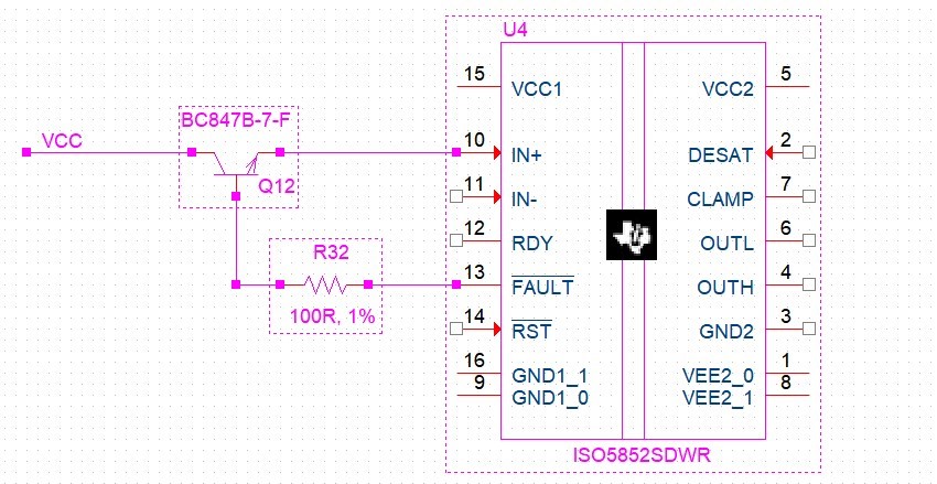
    During the fault condition, when one driver FLT output goes low, all the six driver FLT output goes low. Shall we try the below circuit. ? 

    If we use BC547 to each driver (six drivers are used), Shall we get enough base current from FLT output ? 

    Kindly confirm.

    Thanks & regards,

    Rajasekaran.

  • hi,

    All the FLT outputs are connected together and it was pullup by 10kOhm resistor to Vcc. 

    If we connect BC547 base to the each FLT output (totally six), shall we get enough base current in FLT output terminal ? 

     Kindly confirm. 

    Thanks & regards,

    Rajasekaran.

  • Rajasekaran,

    Using the NPN would pose a challenge, IN+ could reach only ~4.1V at best, with a 10k pullup, it is ~3.8V.  This is unfortunately the problem with NPN as a high-side switch. PNP /would/ solve it, but it would invert your /FLT signal, which we dont want for the inverting global config.

    Have you considered using logic gate to drive IN+ which takes input from /FLT?

    Best

    Dimitri

  • Hi,

    We prepared the pcb now. Is it possible to add any component without major changes in the pcb boards for this time and we will try to use high speed logical and gate next time.

    Kindly could you please suggest any possible solution to achieve the same ?

    Thanks & regards,

    Rajasekaran

  • Rajasekaran,

    Understood. Its unfortunate situation. The 3.8V /will turnon in+ as high, but only barely, there is very little headroom for supply voltage variation you can reduce the 10kohm pullup a bit to increase the IN+ to

    If i understand correctly, you prefer to stick to minor changes (addition of resistor/bjt) to avoid having to drastically change the layout.

    With that in mind: Another suggestion might be to add an an additional PNP to allow VCE ~5V but ensure the polarity of signal is maintained. Would this work work for you?

    Best

    Dimitri

  • And, also consider a small-package 4-6pin buffer. I'm not certain about exactly your layout for this system, but in terms of physical area on PCB it may make more sense to use such a device rather than 2 bjt.
    Best,

    Dimitri

  • hi,

    Thanks for your support to solve the issue. 

    We used BC547 to solve this issue. Vcc is 5.02V, /FLT is 4.98V, IN+ is 4.45V.

    When we used NPN (BC547) and PNP (BC557), the Vcc is 5.05V, /FLT is 4.31V and IN+ is 5.03V. But since the /FLT voltage is dropped, the fault indication LED was always ON. 

    So we are proceeding with BC547 solution for already prepared PCBs. Next time, we will update the circuit. 

    Once again thanks for your kind support. 

    Thanks & regards,

    Rajasekaran.

  • Rajasekaran,

    I'm happy to hear about the solution with single NPN highside switch. 4.45V at in+ should provide enough headroom.

    Let us know if you have any other questions in the future!

    Best

    Dimitri

  • hi,

    Thanks for your help and in our next PCB, will update the circuit :)

    Thanks & regards,

    Rajasekaran.

  • Rajasekaran Sounds good! And youre welcome!

    Best

    dimitri