A related question is a question created from another question. When the related question is created, it will be automatically linked to the original question.
If you have a related question, please click the "Ask a related question" button in the top right corner. The newly created question will be automatically linked to this question.
UCC28950: UCC28950: Where to connect the sense input of ucc29002 when using ucc28950 + ucc29002
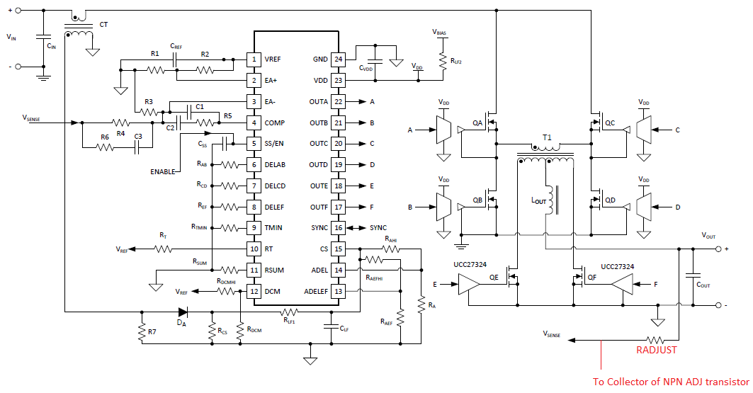
I've marked up the 'typical application schematic' from the UCC8950 schematic below to show how to connect the ADJ output from the UCC29002 to the output voltage sensing of the UCC28950. RADJUST is the same as in your schematic.
The UCC39002 increases the output current of the module it is attached to by sinking a current at its ADJ pin through the NPN transistor. This current causes a voltage drop across RADJUST which 'fools' the UCC28950 controller into thinking the output voltage is lower than it should be. The UCC28950 then increases the module output voltage (by a small amount of course) to increase the output current. All of the UCC39002 controllers are using the same voltage at the LS bus as their reference so the currents are forced to be equal.
If that's not the answer you need then please let me know. Regards
Yes it will - assume you need to provide about 500mV of Vout trimming. Iadj can sink up to 4mA (approx) so RADJ = 500mV/4mA = 125 Ohms. - remember there is almost no current flowing in the output voltage sensing network of the controller. This is a VERY QUICK calculation but the principal is clear. There is an Excel calculator tool available on the product web page at https://www.ti.com/lit/zip/sluc684 that will guide you through the design process.
The UCC39002 increases the output current of the module it is attached to by sinking a current at its ADJ pin through the NPN transistor. This current causes a voltage drop across RADJUST which 'fools' the UCC28950 controller into thinking the output voltage is lower than it should be. The UCC28950 then increases the module output voltage (by a small amount of course) to increase the output current. All of the UCC39002 controllers are using the same voltage at the LS bus as their reference so the currents are forced to be equal.
If that's not the answer you need then please let me know. Regards
Colin
can you elaborate a little more i think i don't understand
Let's say the ADJ pin sinks 2mA. This current flows in RADJUST and causes a voltage drop of RADJUST*IADJ - so let's say 150 Ohms * 2mA = 300mV. The UCC28950 controller will control the voltage at the left hand side of the RADJUST resistor (Vsense in my diagram above ) to be 28V but in order to get 28V at Vsense the output must be regulated up (by the UCC28950 controller) to 28.3V.
The UCC29002 controller can force equal current sharing by slightly adjusting the output voltages of the PSUs in the system so that they are each forcing equal current.
I'd suggest you take some time to look over the .pptx file I posted earlier to try to see if all this makes sense or not (hopefully it should make sense) slide 17 and 18 show RADJ with the voltage drop across it due to IADJ.