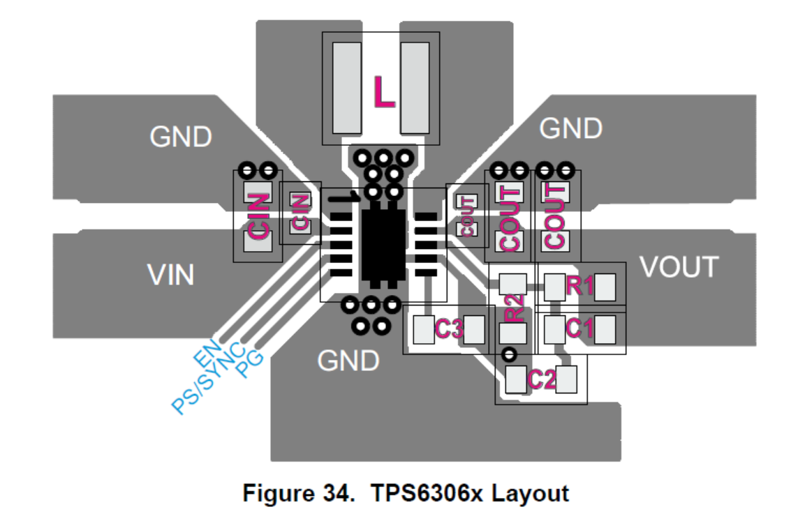
Part Number: TPS63060
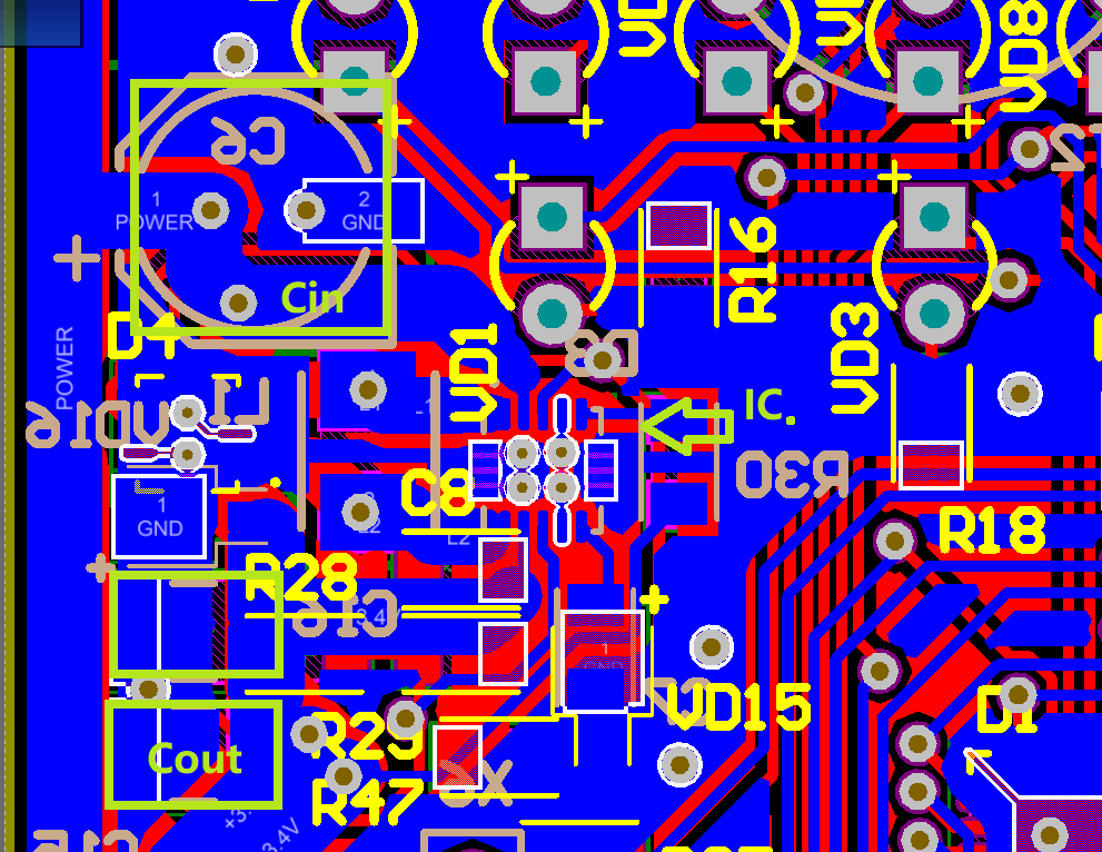
TPS63060DSCR THIS IC is installed on the PCB, some IC input voltage 5.7-7.6 v range, can not work properly. Sampling rate of abnormal 30-35% .

-
Ask a related question
What is a related question?A related question is a question created from another question. When the related question is created, it will be automatically linked to the original question.