This thread has been locked.

If you have a related question, please click the "Ask a related question" button in the top right corner. The newly created question will be automatically linked to this question.

UCD90120A: UCD90120A - Fault response

Part Number: UCD90120A

Hi TI,

We have a strange syptom about fault response of UCD90120A after power off/on system. According to register 0xea, the Rail2, Rail8, Rail9, rail10, Rail11 and Rail12 trigger unexpected fault response as below.

I can understand the Vout UV Fault is triggered from power off system, but I am confused about why some of power rails trigger Vout OV Fault as well.

I think that's impossible behavior because the defaut vaule of Over Fault is 15%.

In addition, what does the SEQ_ON_TIMEOUT mean ? The Rail2 always trigger SEQ_ON_TIMEOUT after power off/on system as well. 

I also provide our settings file as attached, could you help to check whether these unexpected symptom are caused from incorrect settings ? 

UCD90120A 2.3.4.0 Address 52 Project File_NCP1-1_PVT_R02_20191019.xml

Rail2 ---> SEQ_ON_TIMEOUT, Vout UV Fault, Vout OV Fault

Rail8 ---> Vout UV Fault, Vout OV Fault

Rail9 ---> Vout UV Fault, Vout OV Fault

Rail10 ---> Vout UV Fault, Vout OV Fault

Rail11 ---> Voult UV Fault, Vout OV Fault

Rail12 ---> Voult UV Fault, Vout OV Fault

+ ipmitool i2c bus=2 0x68 0xf 0xea
 0e 09 00 02 02 42 02 02 02 02 03 03 03 03 03
+ ipmitool i2c bus=2 0x68 0x5 0xf3
 04 00 00 00 c0
+ ipmitool i2c bus=2 0x68 0x1 0x7a
 00
00000000
+ ipmitool i2c bus=2 0x68 0x1 0x7b
 00
00000000
+ ipmitool i2c bus=2 0x68 0x1 0x7d
 00
00000000
+ ipmitool i2c bus=2 0x68 0x1 0x7e
 00
00000000
+ ipmitool raw 0x3c 0x4 0x9 0x1 0x1
 09 01

// 0x68 is the i2c slave addr of ucd

Thanks.

Blake

  • Hello

    One I noticed that you have the brown-out mode enable which is under Global configuration->Misc Config. Do you have a external brown out circuit(hold up capacitor). Do you ever try to issue clear fault log command when brown out mode is enabled?

    If brown out mode is enabled, application can not issue clear fault log command directly. please refer section 10.26 of https://www.ti.com/lit/ug/slvu352g/slvu352g.pdf?ts=1591114240279

    I would suggest do what section 10.26 to see whether it helps.

    Regards

    Yihe

  • Hi Yihe,

    What does the brown out mode mean ? How to know the brown-out mode enable ?

    Thanks.

    Blake

  • Hi Yihe,

    Yes, we have brownout circuit that includes a Scotty diode and several capacitors to sustain a 3.3V supply voltage.

    We did clear fault (0x3) but never clear logged fault (0xea).

    We can understand the UV Fault event is stored to flash after power off, but we don't have any idea about why Rail2 triggers OV Fault and SEQ_ON_TIMEOUT and  Rail8,9,10,11,12 trigger OV Fault after power off/on.

    Rail2 ---> SEQ_ON_TIMEOUT, Vout UV Fault, Vout OV Fault

    Rail8 ---> Vout UV Fault, Vout OV Fault

    Rail9 ---> Vout UV Fault, Vout OV Fault

    Rail10 ---> Vout UV Fault, Vout OV Fault

    Rail11 ---> Voult UV Fault, Vout OV Fault

    Rail12 ---> Voult UV Fault, Vout OV Fault

    Thanks.

    BRs.

    Blake


  • Hello

    I double checked the settings. Those fault could be historical. I would suggest to

    1. disable the brownout

    2. issue clear fault log command to empty the fault log

    3. enable the brownout

    after above three steps, repeat your power off test to see.

    BTW, what's the hold up capacitor in your design?

    Regards

    Yihe

  • Dear sir,

    We found that the upper threshold of power rail voltage is changed during power rail Vin value polling.

    Sometimes(not always) the upper threshold would be setup lower than the normal reading, for example set 1.5v as a upper threshold for 3.3v power rail.

    The polling rate is 1Hz with following commands, do you have any idea of this?

    // 1. Setup page value for Rail#2
    i2c write 2 bytes 0x00->0x01
    
    // 2. Get the exp value
    i2c read 1 byte after write 0x20 (1byte)
    
    // 3. Get the Vin value
    i2c read 2 byte after write 0x8B (1byte)

    Thanks,

    Jim

  • Hello

    1Hz is very safe to read.

    Do you mean that the OV thresholds was changed during reading? It seems that you have some I2C integrity issue.I would suggest to enable the security mode of UCD so that you will block those write commands to see whether the problem goes away or not.

    Regards

    Yihe

  • Hi Yihe, We just saw the threshold of voltage OV was triggered two or three time. But we can see the OV fault on rail8,9,10,11,12 and Timeout fault on rail3 every time after power off/on. If we stop polling mechanism from BMC, we can’t see these OV fault and Timeout fault anymore. According to my opinion, I don’t think this is SI issue. But of course we can check the signal integrity again. Thanks. Blake
  • Hi Yihe In addition, I think that we just do polling for getting register status . But why does this reading behavior cause the unexpected UV and Timeout fault on specific rails ? If this is a signal integrity issue, I think that we just get failure of reading instead of changing the register status. I want to emphasize the UV fault and Timeout fault can be triggered on every power off/on. We are not sure whether this unexpected fault alarm is related to the threshold of OV fault was changed two or three times on random port. Thanks. Blake
  • Hello

    Integrity issue could make the read come into a write. or your BMC does not follow SMBus Protocol to read. Do you have a waveform for the read operation.

    As you mentioned early, if BMC does not poll, there is no OV or TIMEOUT fault after power cycle.

    I would suggest before your power cycle the board(with BMC polling), launch the GUI to save the project file and compare with your original file to see any differences.

    Regards

    Yihe

  • Dear sir,

    Could you please help to explain how to enable the security mode of UCD?

    As mentioned in the data sheet we need to write the 6-byte password to this register before enabling security.

    Assume the password is "0x01 0x02 0x03 0x04 0x05 0x06", which behavior should we issue to UCD?

    1. Just perform 7-byte data write to offset 0xF1_SECURTY with data "0x01 0x02 0x03 0x04 0x05 0x06 + 0x1"
    2. Or should we need to split to two SMBUS access:
      1. write 6-byte password first
      2. write 0x1 for enabling

    Thanks,

    Jim

  • Hi

    If the password is "123456", you just need send 0xF1 command with 0x06313233343536 to enable the security, resend the same command to disable the security.

    0x06 is the block length, 0x313233343536: is the ASCII of 0x123456.

    Regards

    Yihe

  • Dear sir,

    There are few question:

    1. Since we did not assign the password, I can't enable the security mode by accessing the 0xF1 with default password 0x06FFFFFFFFFFFF. If a modified password necessary? 

    2. Can we change the password and how? via the on-line debug tool or smbus command?

    Thanks

  • Hi

    Please see my comments below.

    #1. you can not use 0xffffff as password. please select other characters

    #2. yes, you can change the password. either one works. first send F1 with old password, then send F1 with new password.

    Please refer section 10.31 of www.ti.com/.../slvu352g.pdf.

    Regards

    Yihe

  • Hi Yihe,

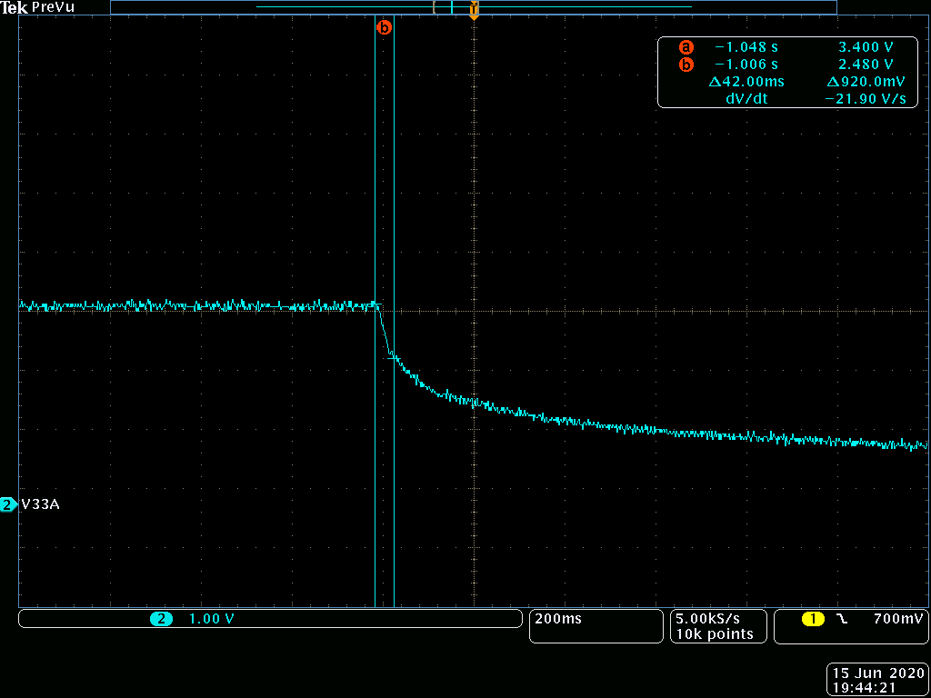
    Could you help to review our brownout circuit as attached pdf file ? I also uploaded the waveform of P33A for checking the power volatge can maintain power voltage 2.5V at least 43ms after power off. 

    After several testings and observation, this issue seems not related to BMC polling or signal integrity.

    I found an interesting symptom about power on system with GUI or without GUI.  The unexpected OV fault and Timeout fault were triggered on every power on without GUI installation. Conversely, no unexpected OV fault and Timeout fault symptom on every power on with GUI installation.

    These unexpected LOGGED_FAULTS seem to be related to the timing of sotring mechanism or someting like that.

    Could you give us some suggestions about this findings ? 

    SCHEMATIC1 _ 103_UCD90120A.pdf

    Thanks.

    Blake

  • Hello

    What's the output voltage of U14? Please be noted that there would be a forward voltage on the diode. if you have a brownout circuit, the input voltage to the diode would be 3.6 instead of 3.3V.  But brownout shall not change the fault type. The brownout is to maintain at least 5ms between 2.9V and 2.6V. Please check this. 

    In the previous post, you mentioned that BMC polling introduced those extra faults. Now, without launching GUI , it introduced extra fault. Do you still have BMC poll without GUI. This does not make sense for me. if there is a signal integrity issue on the I2C, without launching GUI shall make problem go away if BMC does not poll.

    Have your tried the security mode? have your dump the setting to confirm that the OV thresholds are changed indeed?

     Regards

    Yihe