This thread has been locked.

If you have a related question, please click the "Ask a related question" button in the top right corner. The newly created question will be automatically linked to this question.

TPS53626: MathCAD

Part Number: TPS53626

Hi team,

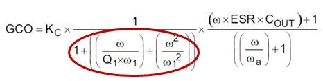
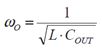
Can I get the MathCAD design tool for TPS53626? I need it for setting control loop parameters. Thank you so much.

This is what DS said : Contact your TI representative to obtain the MathCAD design tool to calculate the stability requirements in this section.

  • Hi KIM,

    MathCAD tool is not available, but you can still follow datasheet parameters for power up.

    Thanks

    Chasel

  • Hi Chasel,

    Can you please provide any materials/reference to check the stability of the TPS53626, other than datasheet? Following DS line-by-line doesn't looks so clear for me as there's even no enough information on DCAP+ architecture.

    The customer got an issue with their output capacitor, the reason of which is from stability I think. So they requested me for a review on the compensation component value. Thank you so much for your help on this!

  • Hi Kim,

    You can use the compensator and platform reference design L/C as a start, then tweak the loop based on transient/DVID performance.

    Thanks

  • Hi Chasel,

    I calculate the pole/zero following the datasheet. Can you please check whether I'm on the right track?

    Q1. 

    Equation above is the control-to-output gain from DS. The denominator highlighted in red looks like Complex Conjugate Pole of the LC Output Filter, so w1 (pole) would be as below.

    But I found the equation for this pole was shown differently in DS as below.

    Can you advise which one is right?

    Q2. 

    I attached a deck, trying to figure out the design process in DS. The loop compensation values (R1, C1, C2) are not as I expected. I add questions/note in the blue color. Can you review the deck and give me some comments? 

    0842.TPS53626_Stability_DS.pptx

    Once you confirm it, I would go for the customer schematic with the same approach. Thank you so much for your support on this!

  • Hi Kim,

    1. Omega1 = pi / Ton

    2. You can design the zero close to fo without issue, but for the high frequency pole, please move it around the switching frequency, if it is at low frequency, you will get lower bandwidth and harm the transient performance.

    Thanks

    Chasel

  • Hi Chasel,

    Thank you so much for your time! Could you please answer for my last question?

    Regarding your answer 1, how do I get Q1 then? I thought it was Q factor of output filter with Omega0 as below, but you told me Omega1 is correct, how can I calculate Q1?

  • Hi team,

    Would you kindly answer to this question? Thank you.

  • Hi Minkyung,

    Usually there is mismatch between calculation and measurement due to component variation, board parasitic and etc. 

    I would suggest to tune compensation with bench test. 

    Thanks

    Qian