This thread has been locked.

If you have a related question, please click the "Ask a related question" button in the top right corner. The newly created question will be automatically linked to this question.

BQ25606: Power path problems

Part Number: BQ25606

Hello,
I chose this device to power a microprocessor that works at 3.6Vdc (with average currents of 600mA (at 3.6Vdc) with peaks of 2A.
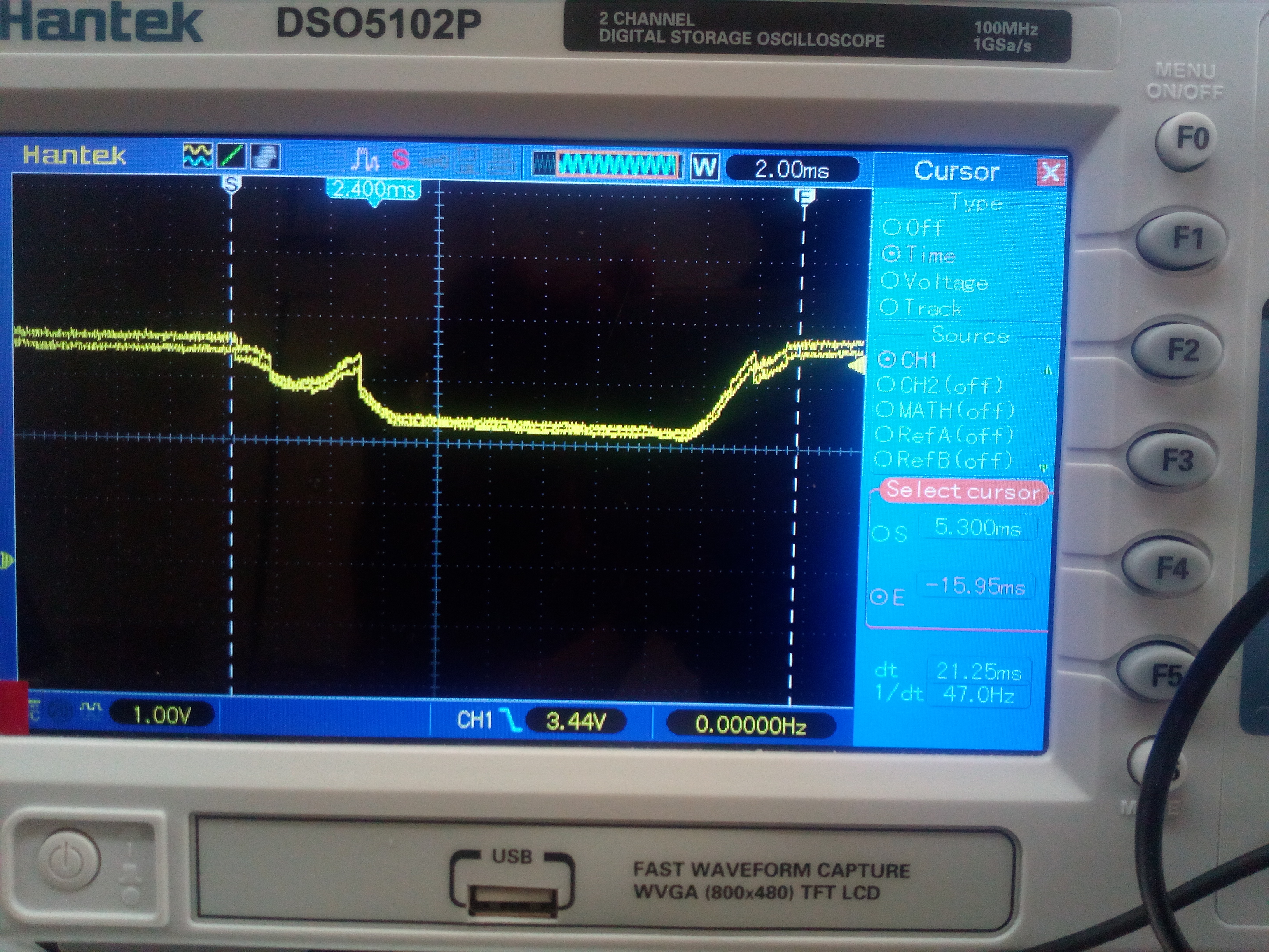
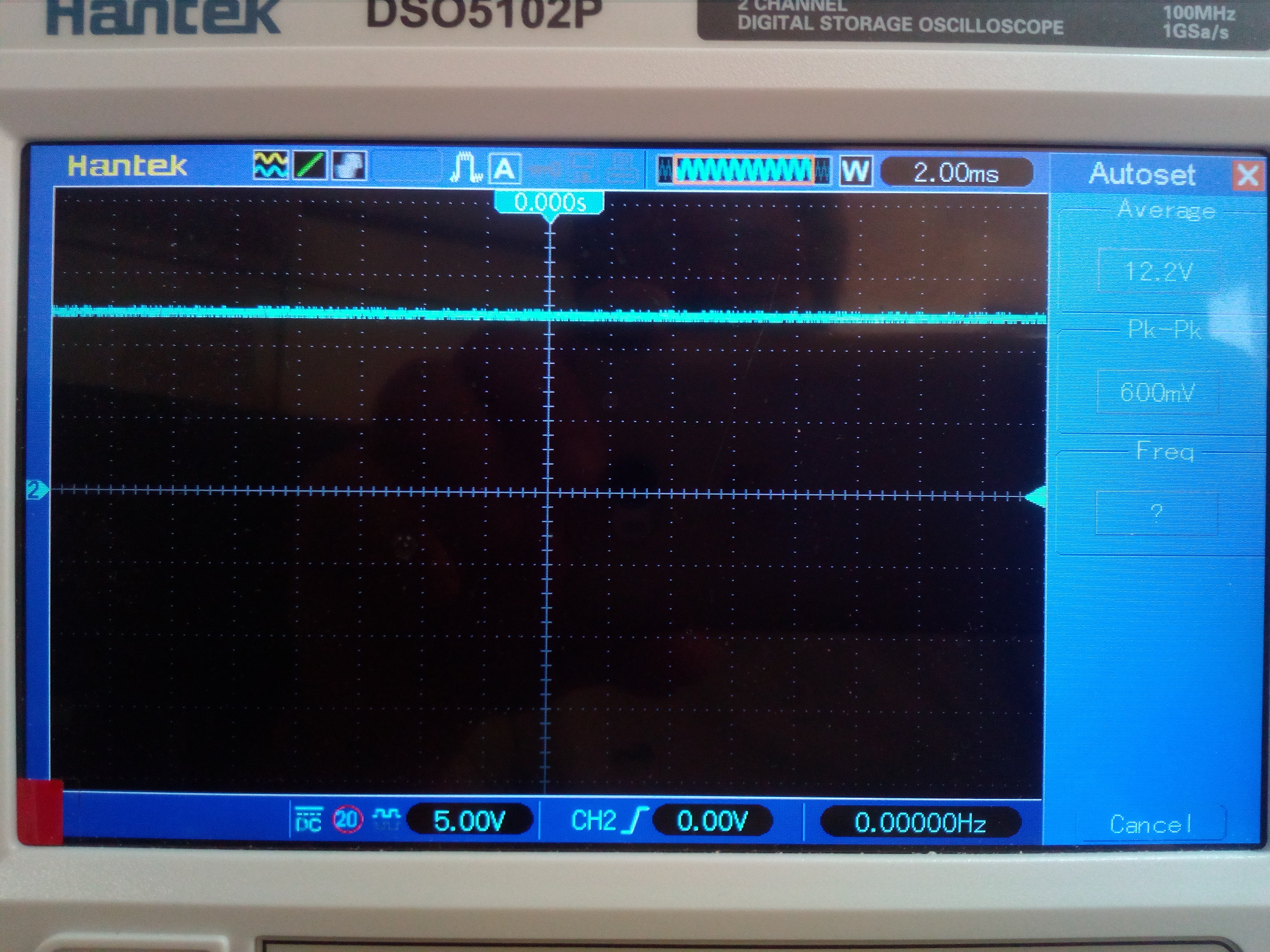
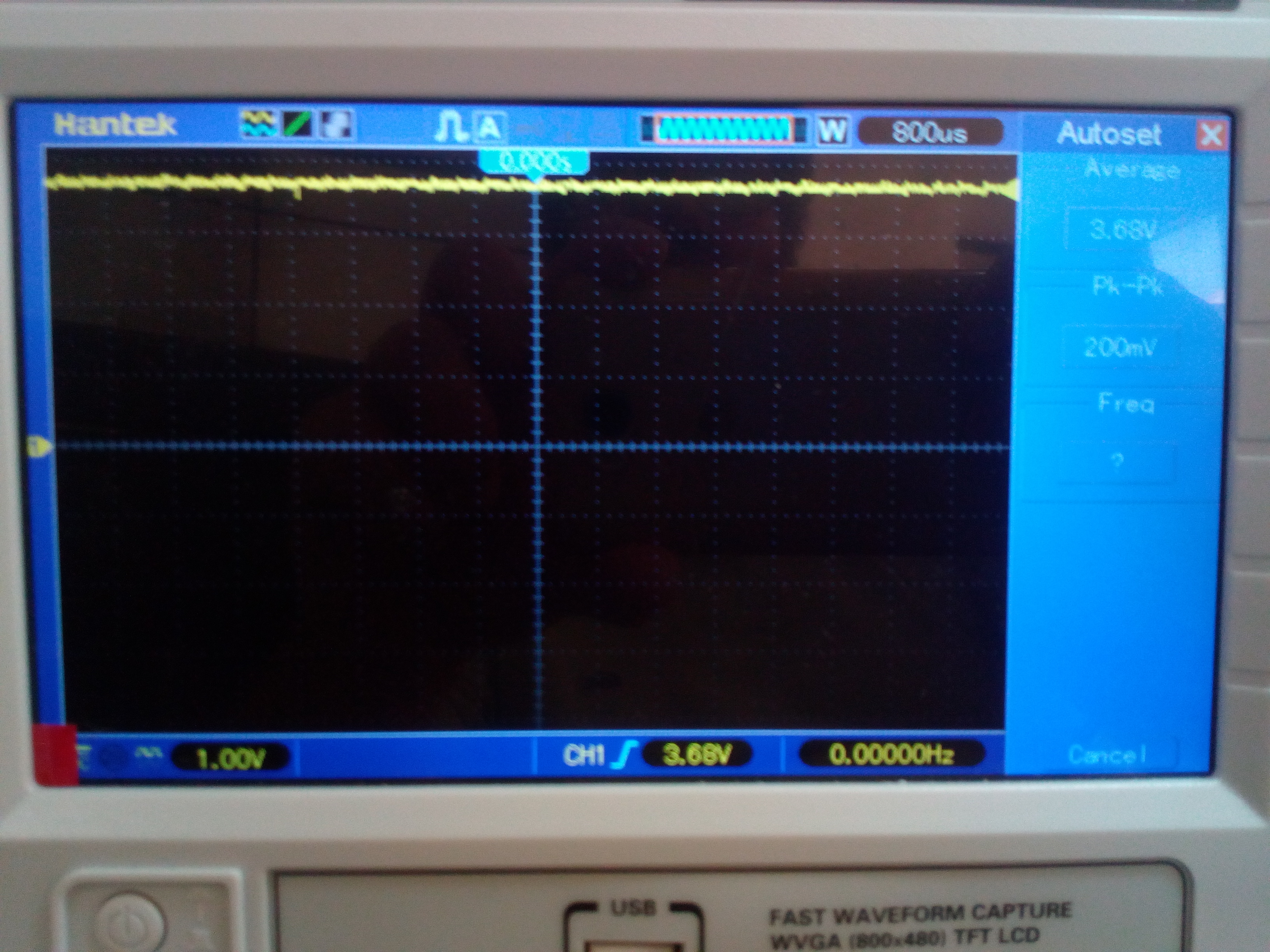
My intent is to use it both with and without lithium battery connected, but, if the battery is disconnected, I detect at Vsys a voltage drop of about 1.38V, for the duration of about 20 msec, which resets the microprocessor.
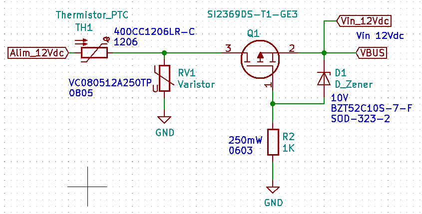
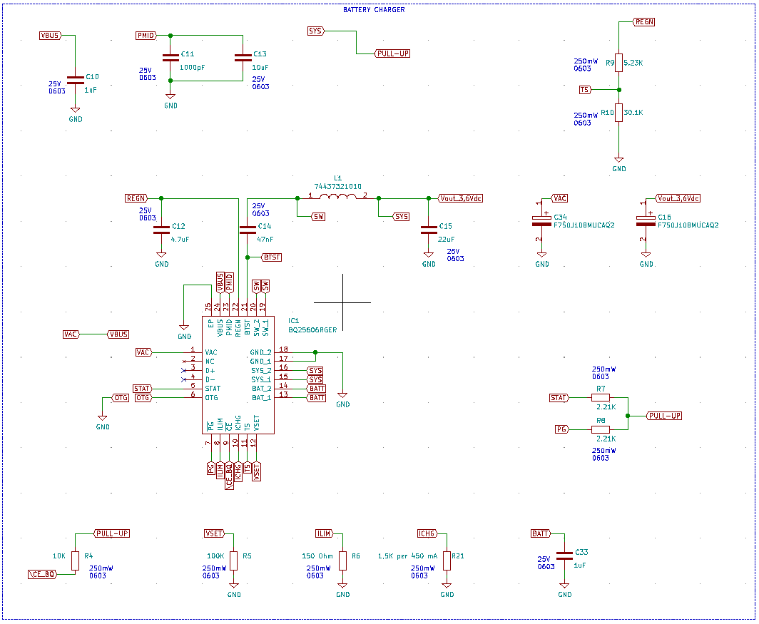
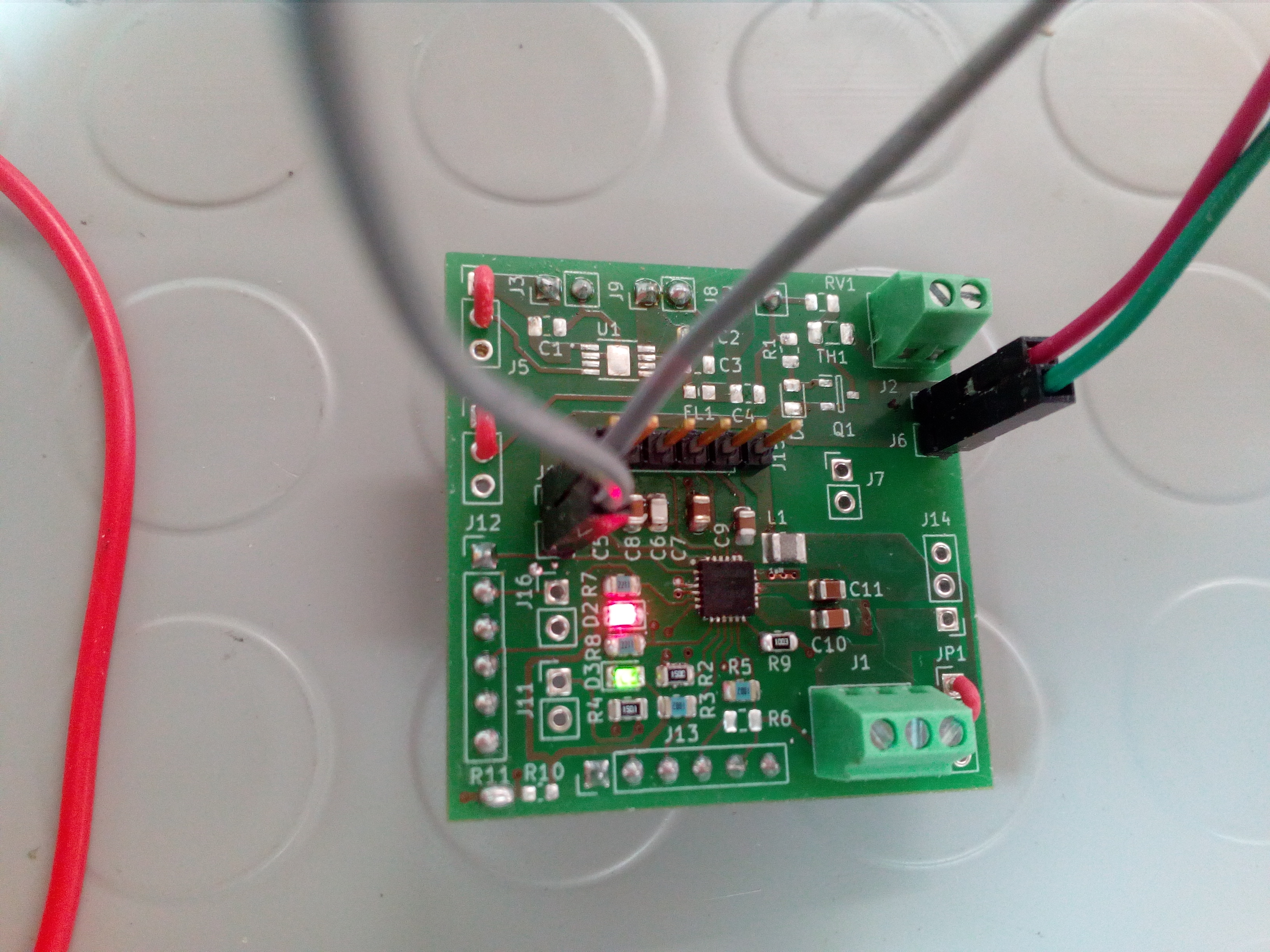
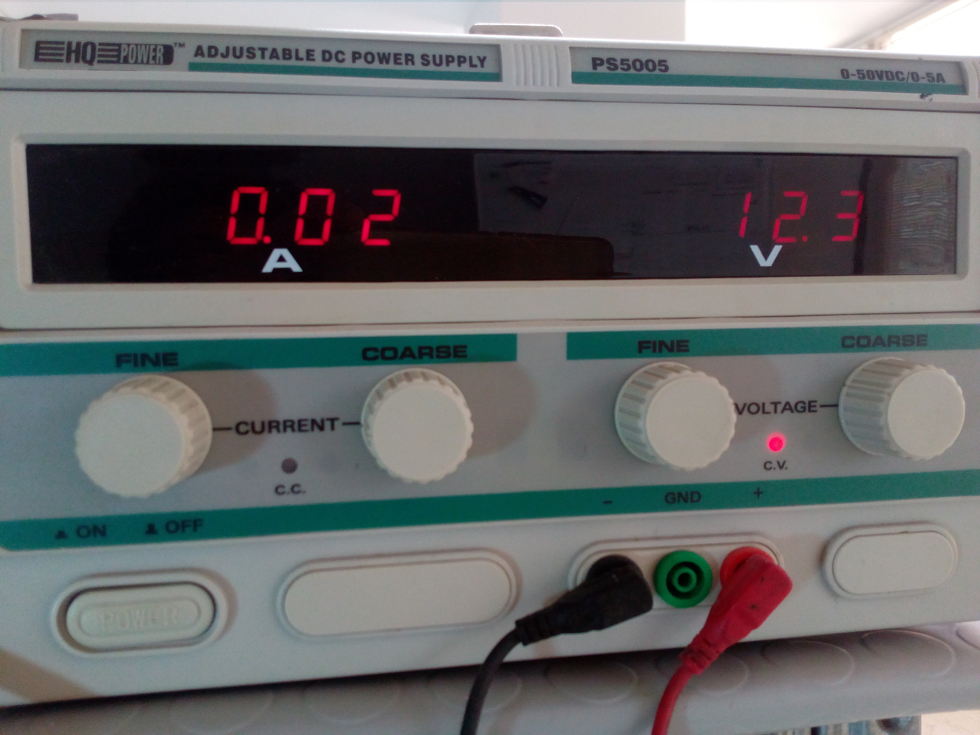
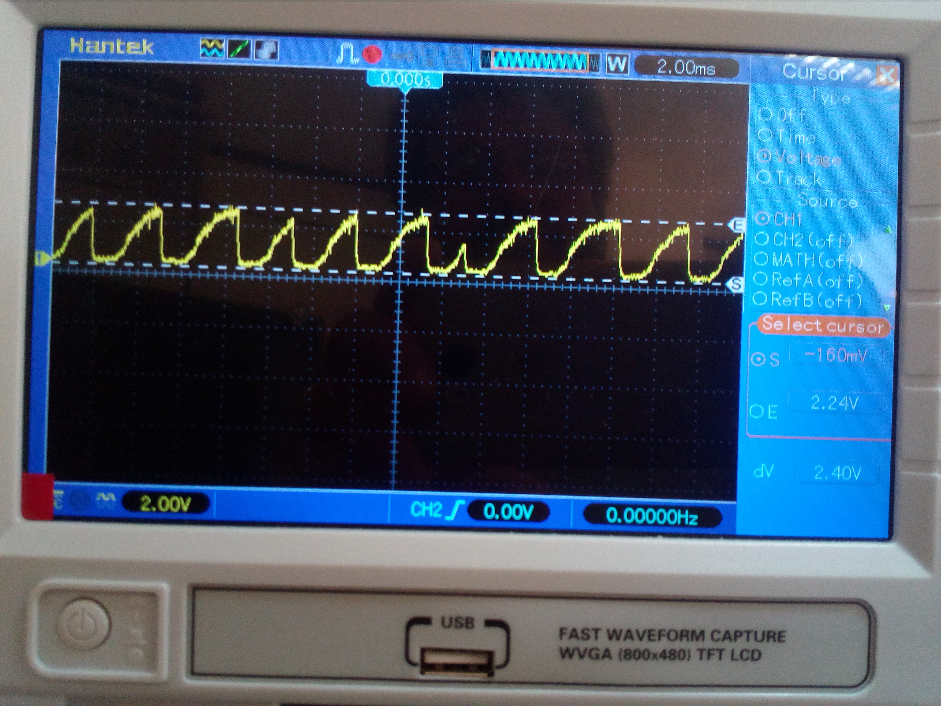
I attach the schematic and photos of the tests done on the Vsys.
From the datasheet, the bq25606 should be able to deliver up to 3 A even in the absence of a battery.

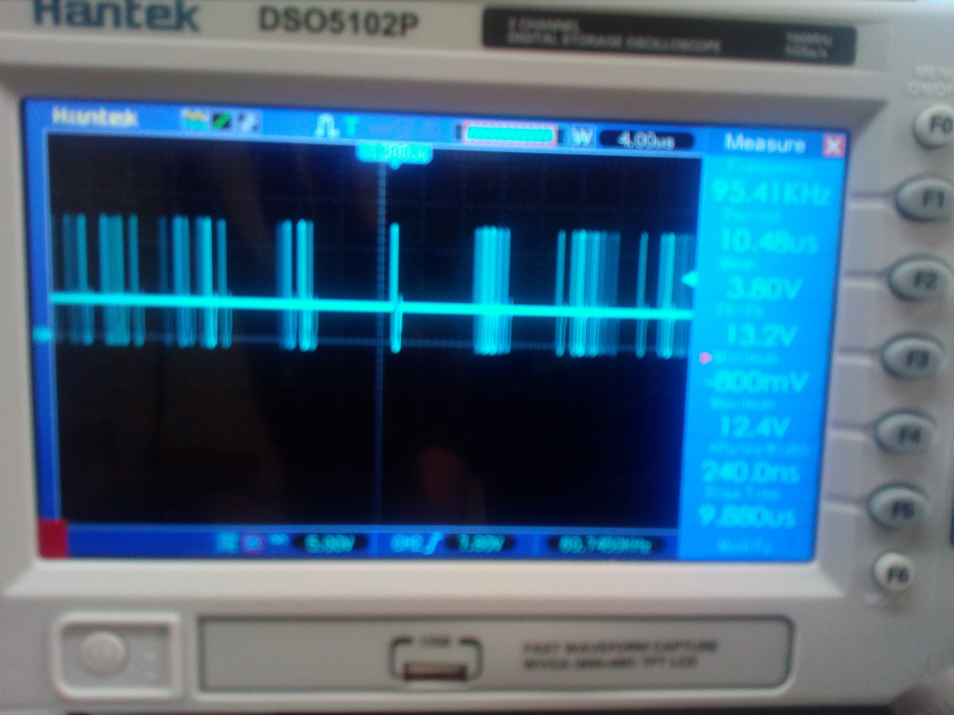
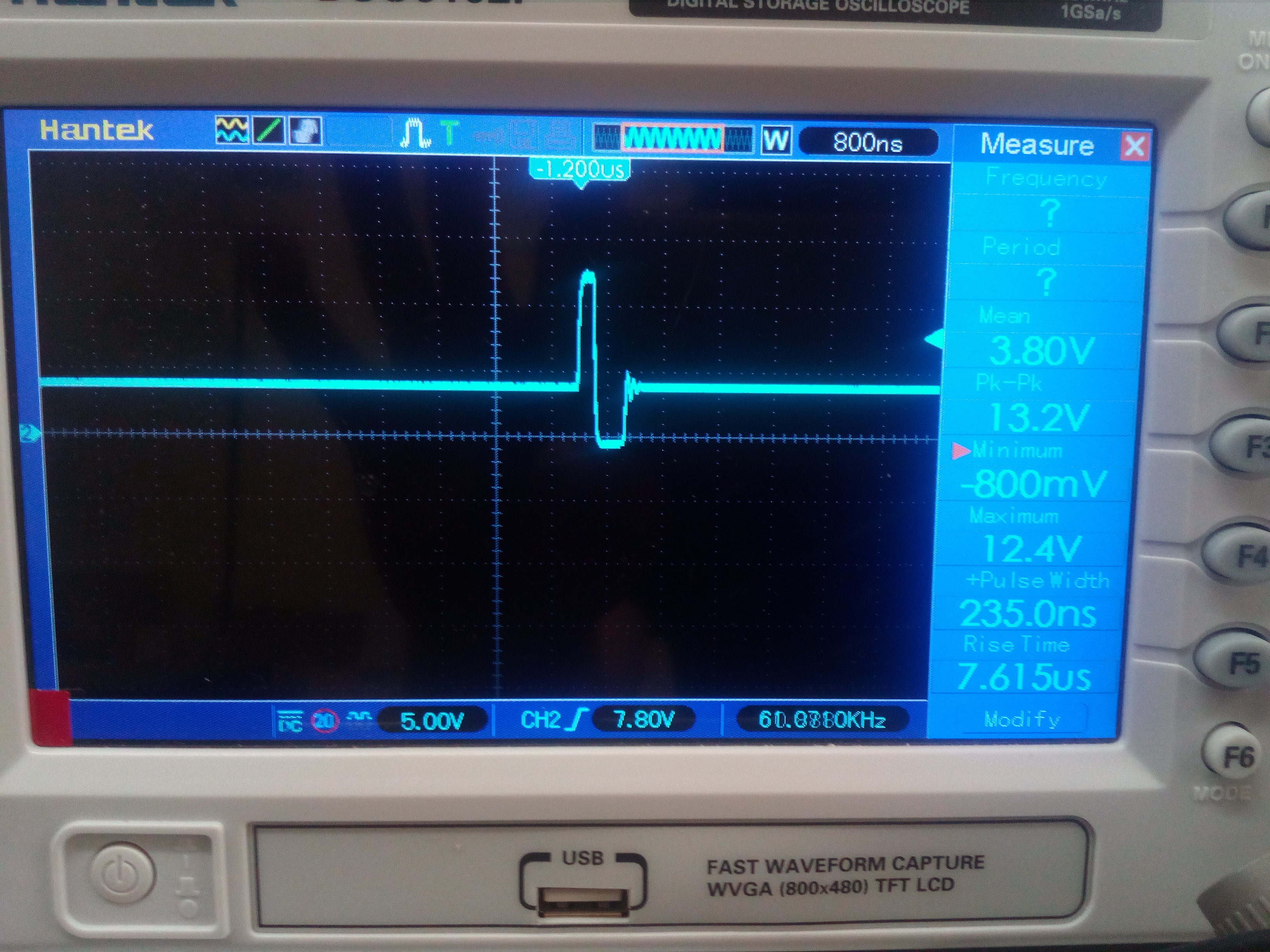
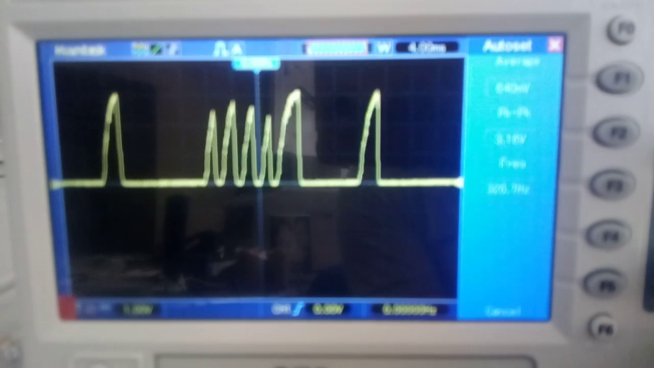
Also, if I measure the SW, I don't see a square wave as per the datasheet.

I'd like to understand where I'm wrong.

Thanks for your help

1273.Schematic BQ25606.pdf

  • Hi,

    Please visit https://e2e.ti.com/support/power-management/f/196/t/890626 for BQ25606: Schematic Review and PCB Layout Design Tips. Additional Information including FAQs is available http://www.ti.com/lit/an/slva924/slva924.pdf Designing A Standalone Single Cell 3-A Charger with the bq25606. The FAQ "When battery is not connected, that is, BAT pin is floating, why does the STAT pin blink?" should be helpful for you.


    Referring to 8.3.2.5 Converter Power-Up on the d/s,  The device provides soft-start when system rail is ramped up. When the system rail is below 2.2 V, the input current is limited to is to 200 mA. After the system rises above 2.2 V, the device limits input current to the value set by ILIM pin. Do not apply more than 200mA load at VSYS when VSYS<2.2V.

    Thanks,

    Ning.

  • Hi Ning,

    Thank you for answer,

    I have read the documents you have indicated to me, but I have not found an exhaustive answer regarding what I see during the test of my circuit.

    I describe in more detail how I set up the circuit of the BQ25606 and what I see from the tests I did:

    - /CE at VSYS, via 10k pullup resistor (charge disabling);

    - TS Voltage fixed with voltage divider (R5 5.23K, R6 30.1K);

    - 47nF Capacitor between btst and sw;

    - 1uH inductor 74437321010 Wurth Elektronik (Isat 7.5A);

    - 22uF Capacitor between sw and sys;

    When I power on the system (power circuit and microprocessor circuit) with Vbus 12.5 Vdc (without battery), I can see Vsys 3.68Vdc (Vsysmin+ 180mV, as described in  the document you have indicated "Designing A Standalone Single Cell 3-A Charger with the bq25606" at the FAQ:  "How is VSYS regulated in buck mode with valid VBUS?").

    In the initial phase the system  does not draw much current (about 300 mA at 3.6 Vdc) and the power supply circuit works well.

    When I enable the upload transfer (my system is an IOT system) and then the microprocessor circuit requires a current with peaks higher than 1A, up to 2 A, I see the Vsys which drops 1.5 V for a short moment (approximately between 13 and 22msec) . In this way the power supply voltage of my microprocessor circuit drops below its minimum value, and the microprocessor system resets, to reactivate immediately afterwards as the Vsys has returned to 3.68 V.

    If I repeat the test with the battery connected (charged and therefore always with CE disabled) the Vsys I see is about 4 V (VBAT + 50mV) and I don't see the voltage drop that I saw in the previous case.

    If the battery is low ( and therefore I must enable CE pin)   the power supply circuit, during the upload phase, cannot keep the Vsys at 4.2V and the power supply voltage drops below that of the microprocessor threshold (the current is still less than 3A because I set the Ichg to maximum 500mA with Rchg of 1.5K)

    Is it possible to use the BQ25606 without battery with output current up to 3A?

    Can this device track rapid changes in output current?

    Where am I wrong?

    Thanks for all the help you can give me

  • Hi,

    What are your test conditions such as VBUS (voltage at VBUS pin), IVBUS, VBAT (voltage at BAT pin), IBAT, VSYS, ISYS when the behavior happens?


    Please check if STAT pin indicate any faults and debug from there. STAT pin blinks when Charge suspend (input overvoltage, TS fault, timer fault or system overvoltage). Please also check if the input source is over-loaded, either the current exceeds the input current limit or the VBUS pin voltage falls below the input voltage limit.


    Thanks,

    Ning.

  • Hi Ning,
    thanks for your help.
    I'm currently using a stabilized power supply that can deliver up to 5A.
    The circuit should be powered with 12Vdc VBUS, but I did several tests with different VBUS.
    Specifically, upstream of the BQ25606 I have inserted a protection circuit against voltage inversion and overvoltages, as shown in the figure, which performs its work from tests carried out.
    I noticed that by inserting an electrolytic capacity of 1000uF between the protection circuit and BQ25606 and an electrolytic capacity of 1000uF at the output (at Vsys) the system improves (I now see a drop in voltage at the VBUS, always 1.5 Vdc, but for a period of time about 3 msec).
    If I use as VBUS 6 Vdc, the system works without errors.

    If I use different voltages (even 5 Vdc or 7 Vdc) I find the same error.

    the 47 nuF capacity between btst and sw is not of the X7R type

     I'm waiting for your feedback

    Best Regards

  • Hi,

    1. Are you testing with real battery or battery simulator?

    2. For debug purpose, could you please remove any circuitry unrelated to the basic operation of the BQ25606 so that we may focus on BQ25606 behavior?

    3. What are the test conditions such as VBUS (at VBUS pin), IBUS, VBAT, IBAT, VSYS, ISYS when the charge works normally and abnormally? If ISYS on the board is not constant, please disconnect and use external resistor box as SYS load.

    Thanks,

    Ning.

  • Hi,

    1) I'm testing with real battery, Lipo Battery 3,6Vdc 1000mAh. When I connect the battery the BQ25606 works fine (but I se that the necessary current is absorbed mainly by the battery).

    2) I have already done tests only with the BQ25606 and the problem seems to be due to it, or rather, to the Vac which is a sense of Vbus. When the battery is not connected I see a voltage drop (13 msec) and the pg goes high. By putting an electrolytic capacity of 1000 uF on the VBUS, the time interval has decreased to 3 msec.

    3) :

    VBUS = 12 Vdc;

    IBUS = about 0,6A

    VBAT and VSYS like the foto with  the voltage drop (the lipo battery is not connected)

    I also tried connecting, instead of the microprocessor board, 3 resistors of 1 Ohm 10Watt (at 3.68 Vdc the absorbed current is about 1A).
    The result is that I saw that the BQ25606 without a lipo battery was unable to supply the load (Vbus could not remain at 3.68 V but dropped to less than 2 V and the LEDs connected to PG and STAT became dim.

    In another test I've inserted 2 tantalium capacity of 1000 uF, one at VBUS and the other at Vsys and the system seems work fine.

    Before finalizing the circuit I would like to understand if you have detected my own problems in using the BQ25606 without battery and with loads with currents of about 2 A (this is my purpose).

    Thanks for all the help you can give me.

    I'm waiting for your feedback

    Best Regards

  • Hi,

    What is your input current limit setting (IINDPM)? Please refer to Table 2 Input Current Limit Setting from D+/D– Detection on the d/s for the details.

    Thanks,

    Ning.

  • Hi,

    The pins D+ and D- aren't connected in my schematic,

    I put a 150 Ohm resistor to gnd at ILIM pin (see schematic)

    I'm waiting for your feedback

    Best Regards

  • Hi,

    There is some circuitry unrelated to the charger in the system. Please disconnect these circuitry, test the BQ25606 charge only using 12V lab power supply and 2A resistive load at SYS pin and see if it works normally.

    Thanks,

    Ning.

  • Hi,

    We haven’t heard back from you for a while, the thread is considered solved and closed.

    Thanks,

    Ning.

  • Hi Ning,

    I'm sorry if I haven't been able to answer so far, but I couldn't do the test you asked me again.
    Now I run it and show you the results (which I had already had before).

    Below photos and videos with a description of what I did and device adjustments

    1) pcb photo, as you can see I have removed all the circuits upstream and downstream of the bq25606. I powered the circuit by Vbus (12.3 Vdc), no load connected and battery not connected. As you can see from the video, the circuit works well.

    Now I am going to connect (always without the battery connected) two 1 Ohm resistors in series, which, with a Vsys voltage of 3.68 Vdc, should absorb a current of about 1.84 A:

    This is what happens (see the photo and two videos below):

    Vsys:

    Thank you for your help

    I'm waiting for your feedback

    Best Regards

  • This is the video of what I see on the oscilloscope (Vsys), always with the battery not connected:

  • Hi Ning,

    I'm sorry if I haven't been able to answer so far, but I couldn't do the test you asked me again.
    Now I run it and show you the results (which I had already had before).

    Below photos and videos with a description of what I did and device adjustments

    1) pcb photo, as you can see I have removed all the circuits upstream and downstream of the bq25606. I powered the circuit by Vbus (12.3 Vdc), no load connected and battery not connected. As you can see from the video, the circuit works well.

    Vbus:

    Vsys:

    Now I am going to connect (always without the battery connected) two 1 Ohm resistors in series, which, with a Vsys voltage of 3.68 Vdc, should absorb a current of about 1.84 A:

    This is what happens (see the photo and two videos below):

    Vsys:

    Thank you for your help

    I'm waiting for your feedback

    Best Regards

  • Hi,

    What are your test conditions such as VBAT (voltage at BAT pin), IBAT, VSYS, ISYS? The pictures only show VBUS=12V and IVBUS=20mA. And what are the waveforms?

    Thanks,

    Ning.

  • Hi Ning,

    Without load:

    Vbus = 12,2 Vdc

    IVbus = 20mA

    Vsys = 3,68 Vdc (like the fourth photo that I inserted)

    Vbat = 0 Vdc (/CE is pulled up to Vsys, recharging is disabled, no battery is connected)

    IVbat = 0 A  (/CE is pulled up to Vsys, recharging is disabled, no battery is connected)

    IVsys = 0 A (no load in connected)

     With load: (2 Ohm 10 Watt):

    Vbus = 12,2 Vdc

    IVbus = see this video:

    Vsys = see this video:

    IVsys = see this video:

    Vbat = see this video (/CE is pulled up to Vsys, recharging is disabled, no battery is connected):

    Ivbat = 0 A (/CE is pulled up to Vsys, recharging is disabled, no battery is connected)

    I'm waiting for your feedback

    Thank you for the help

  • Hi,

    You mentioned Vsys = 3,68 Vdc , SYS load: (2 Ohm 10 Watt). Why Isys is only ~0.27A?

    Thanks,

    Ning.

  • Hi Ning, 

    No, I see Vsys at 3,68 Vdc only when there is no load (2 Ohm 10 Watt) connected, and so I can see Vsys= 3,68 Vdc , Ivsys= 0A (it's all right);

    When i connect the load, I see this waveform (Vsys):

    See this video (Vsys):

    And so Ivsys= 0,27A

    This is the problem, The BQ25606  cannot supply, with this load, 3.68 Vdc and 2 A currents ( if no battery is connected)

    I'm waiting for your feedback,

    Best Regards

  • Hi,

    Referring to page 9 of the d/s, the IINDPM is set to 200mA initially when SYS starts up.

    If the charger is powered up without the battery, VSYS will start from 0V and may stuck in 200mA IINDPM if SYS tries to pull too much current during start-up. Please do not apply more than 200mA load at VSYS when VSYS<2.2V.


    Thanks,

    Ning.

  • Hi Ning,

    what you wrote is right when I turn on the system with the load already connected, but the problem also occurs when I connect the load after turning on the BQ25606 with a switch (so when the start-up sequence should have finished).

    I read about a thermal protection (page 22 datasheet).

    Could this be the cause?

    I'm waiting for your feedback

    Best Regards

  • Hi,

    Did you measure the IC surface temperature?

    Thanks,

    Ning.

  • Hi Ning,

    no i didn't measure the IC surface temperature,

    but touching the device, I did not experience any heat.

  • Hi,

    It should not due to thermal protection if the IC temperature is low.

    It is highly recommended to get familiar with the device operations by testing the device EVM and compare the EVM behaviors with your customized board for debugging.

    Thanks,

    Ning.