Because of the holidays, TI E2E™ design support forum responses will be delayed from Dec. 25 through Jan. 2. Thank you for your patience.

This thread has been locked.

If you have a related question, please click the "Ask a related question" button in the top right corner. The newly created question will be automatically linked to this question.

BQ24780S: System don't charge the batterie

Part Number: BQ24780S

Hello,

this chip (BQ24780S) is present on a laptop motherboard (Asus UX305CA), but it seems not to want to charge the battery.

The computer runs on mains power, and also runs on battery power.
BUT does not charge the battery (it discharges itself until it doesn't work anymore).

I've tested the circuit continuity, and everything looks OK, plus no short circuits.

So I suspect this chip, but I don't know enough to tell if it comes from this chip or from another damaged component (resistance?)

I noted the voltages in operation with Charger + battery, and I wanted to know if the values I find are coherent or if you see something that could explain the problem...

Charger 19.5v , Battery at 11.43V

Pin 1: 19.38v
Pin 2: 19.38v
Pin 3: 19.34v
Pin 4: 19.38v
Pin 5: 1.65v
Pin 6: 0v
Pin 7 : 0v
Pin 8: 0v
Pine 9: Unknown
Pin 10: 0v
Pin 11: 3.26v
Pin 12: 3.26v
Pin 13: 0v
Pin 14: 0v
Pin 15: 1.1v
Pin 16: 11.37v
Pin 17: 11.37v
Pin 18: 11.30v
Pin 19: 11.37v
Pin 20: 0v
Pin 21: 0v
Pin 22: GND
Pine 23: 0v
Pine 24: 6.02v
Pine 25 : 11.03v
Pine 26 : 11.36v
Pine 27 : 11.36v
Pine 28: 19.14v

Thank you in advance.

Best regard
Thomas C.

  • Hi Thomas,

    Pin 3  (CMSRC): 19.34v
    Pin 4  (ACDRV): 19.38v

    This the values of these two pins may be why you have an issue.  I would need to see the motherboard schematic to know for sure, but generally ACDRV is attached to an N-channel MOSFET that is used to block the adapter from the system.  In order to turn the pass FET on, ACDRV is driven 6V above CMSRC.  With the measurements you are showing now, that FET will be off.  In this state the motherboard is running purely off the battery and the adapter is cut off from the system.

    The condition to turn the FET on is that ACDET (pin 6) is above 2.4V.  You show it as 0V.  Usually this is a simple resistor divider that divides down the adapter voltage, so if you are reading 0V, then maybe one of the resistors in the divider got damaged, although that would be a rare occurrence.  Again, it is difficult to know the possible cause without seeing the schematic.  But these measurements are consistent with your description that it doesn't charge even though the adapter is plugged in.

    Regards,

    Steve

  • Hi Steve,

    First, thank you for your great help :)

    I am attaching the two documents I have (a PDF and a .FZ for boardview) to this answer.

    I lack knowledge in electronics but I'll do my best to understand :)

    Edit : after further testing, Pin 6 is at 2.6V

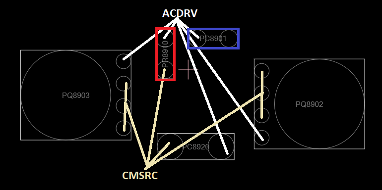
    Edit 2 : I've checked again and I may have a lead, on the charger, I've got this schematic:
     
    I was able to identify the items directly connected to ACDRV and CMSRC.
    The PC8901 (blue) and PR8910 (red) components have been removed and replaced by a single wire because they were damaged... can this be the cause? (PR8910 = 4.7 Mhom resistor and PC8901 a capacitor)...


    Edit 3 :  if I put Pin 3 at 0v (cut it off), can that solve my problem? (even if it's not clean)...

    Best regards,

    Thomas C.

    ASUS UX305CA RG.pdffixbios.com_UX305CA.zip

  • Hi Thomas,

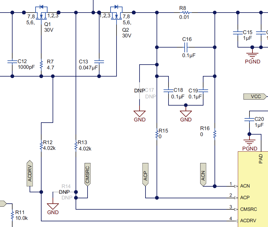
    I think that the diagram that you show above corresponds to the soft-start circuit here on our EVM:

    Then based on the connections in your diagram, I think PC8920 = C13, PR8910 = R7 and PC8901 = C12. 

    Ideally, if one or more of the components was damaged, you would replace them with like components.   I am not sure what replacing with wires is going to do, but I can tell you that the capacitor needs to be left open circuit and only the resistor wired over if that is how you are going to try and repair it. 

    You said that the capacitor and resistor were both removed and replaced with a single wire because they were damaged.  If this is the case, the wire needs to only connect the two pads of the resistor.  You should see both pads of the capacitor open.  If you short over either C12 or C13, it would prevent ACDRV from turning on the FETs because it would be shorted to CMSRC.  This seems to be the issue you are reporting, so I would definitely say to double check that whichever capacitor was removed, you haven't shorted over that capacitor with the wire.

    Also, I just need to point out that replacing these components with a wire is not a configuration that is supported by TI.  I can give you advice to help you debug what you are seeing, but I am not recommending that you repair the board in this way.  These components should be replaced by new components to repair the board properly.

  • Hi Thomas,

    I haven't heard from you in a few weeks, so I am going to assume you were able to resolve your issue and close the ticket.  You can re-open the ticket if you have further questions.

    Regards,

    Steve