This thread has been locked.

If you have a related question, please click the "Ask a related question" button in the top right corner. The newly created question will be automatically linked to this question.

BQ20Z90EVM Problem

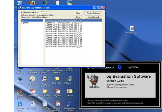
I setup the BQ20Z90EVM according to the SLUU234 Users Guide, I also followed the application report SLUA335B.


I am using 2 cell li-ion battery pack without any protection circuit on them.


I connected them as shown with 1N connected to the negative of the series pack, 1P connected to the "centertap" of the series pack, and then 2p connected to the top of the series pack (also jumpered together with 3p and 4p).

I applied a voltage (about 10V) across pack + and pack - to "wake up" the system. I connected SYS PRES to VSS

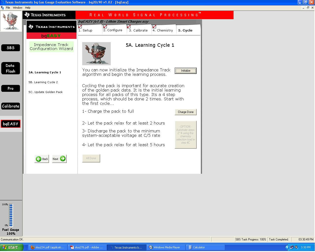
The EVM communicates properly with the computer software (EVM software) but when I try to go through the Bq easy so that I can create a golden file for my battery pack I cant seem to chage the battery through the evaluation board.

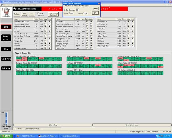
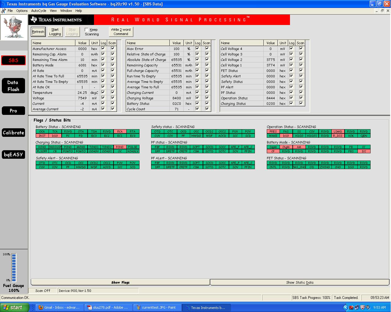
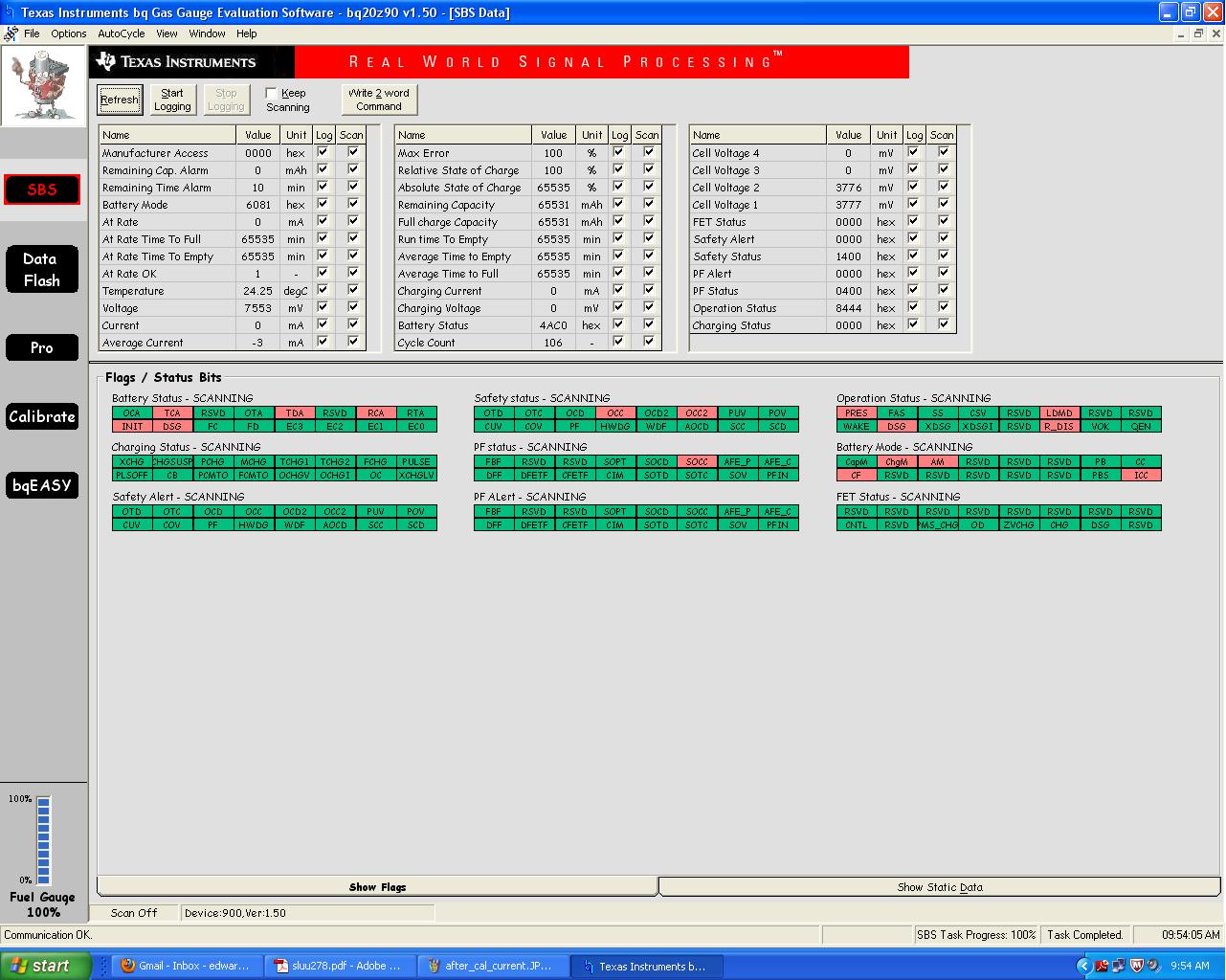
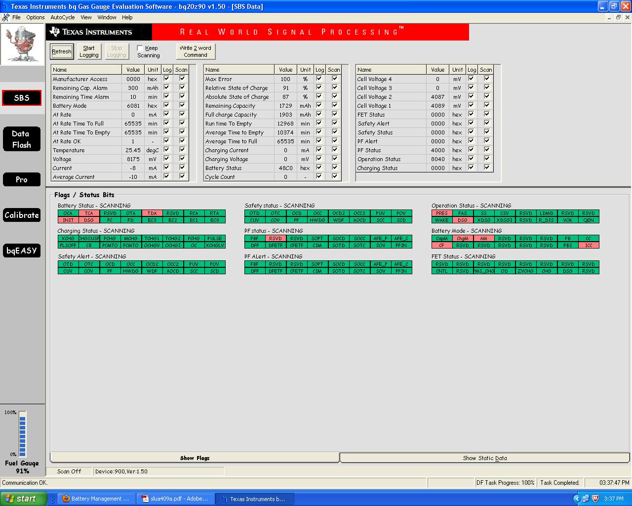
I then noticed that  I could not read my battery voltage across TB3 and TB4 but it was clearly across TB1 and TB2 also I could trace it on the board to confirm it wasnt just on the terminals.

It appears as Q4 the "DSG" fet is off blocking the path from the battery to TB4.

Any help would be appreciated, I am just wondering if I am missing a step or doing something wrong.


Thank You.


  • Hi Edward,

    Have you initialized the Impedance Track algorithm? Clicking on the "Initialize" button in step 5A of bqeasy should enable the FETs and allow charging. If you can't charge after enabling IT, please post a screenshot of your SBS screen.

    Regards,

    Antonio 

  • Yes I have clicked initialize button on step 5a of bqeasy. I have attached 2 screen shots. I was still not able to charge after clicking Initialize.

    Also do I need to follow the instructions in SLVA208B ( i am using 2 cells) or will the bqeasy make all the changes

    described in SLVA208B automatically?


    Thanks for the help, I await your reply.


  • Edward,

    You have a permanent fail flag, which prevents you from progressing. Any idea what caused the over current in charging flags? You can clear it by typing 2673 1712 into the "Write 2-word Command" box available near the top of the SBS screen. 

    Rgds,

    Doug

  • Which flag is the permanent fail flag (for future reference) ?

    I have no idea what caused the over current in charging flags, I will clear and try again.


    Thanks,


    Eddie


    I tried to clear the flag but do not believe I was able to do so.

  • Hi Eddie,

    The permanent fail flag is SOCC (safety overcurrent charge) under PF status. It is set when the current is equal to or higher than the SOC Chg threshold for a time period that exceeds the SOC Chg Time. Pages 121-122 of the TRM (https://focus.ti.com/seclit/er/sluu251/sluu251.pdf) explain this in more detail. Sending the Permanent-Failure-Clear command (sec. B.16, page 96 of the TRM), as Doug mentioned, should clear the flag.

    Regards,

    Antonio

  • Antonio thank you for the link to that document, I never found it on TI's website.

    I am going to spend some time reading it to see if I am missing something but for now...

    I have attempted to clear the flag but it doesnt seem to clear.

    I also tried writing "62" in the SMBus command but that did not seem to help either.


    I have no load hooked up to the evaluation board at all. I have went through the steps in the bqeasy multiple times

    and each time end up with the SOCC flag being set.  Ive tried powering the device on and off and restarting the

    evaluation software.


    I am simply trying to evaluate these two IC's to use as a gas gauge/protection  for 2 lithium cells in series.


    thanks for the help, I have attached a second jpeg, you can see that the first and 2nd tier OC thresholds are at 0mA

    I tried to set them to 2000mA but could not, even after going through setting up bqeasy these values remained at 0.

    Eddie

  • Eddie,

    It looks like your board has an old version of the z90 firmware on it. I'm not sure how v1.02 made it onto the board, but I have attached the latest, v1.50, for you to load to the gauge.

    To load the firmware, follow the steps below:

    1. Go to the Pro Screen in EVSW and put the device in ROM mode. ROM mode can be entered by writting 0F00 to command 00.


    2. In the Srec Programming section, click the ellipsis and open the file I attached.

    3. Click program. You will see a status bar indicating the progress.

    4. When it is done programming, click OK.

    5. Close EVSW and then reopen it.


    If the EVSW does not auto-detect the firmware version, you will need to update EVSW.

    Try using bqEasy again. Hopefully the issues go away. If not, we may need to take a look at the exact procedure you are following.

    bq20z90_1_50.senc
  • I updated the firmware and the evaluation software could not see the device.

    It read the device as "1717_17_17".

    The installer I used for this software was "bqEVSWSetup00.09.59_bq20z90v1.50_bqEasy1.85.exe"


    Is there a more recent version of the bq evaluation software?


    Thanks


    Eddie

  • Hi Eddie,

    After you program the gauge, you need to exit ROM mode. In order to do that, open the EVSW, select v1.50 on the pop-up window (as shown on your screenshot), and click on "Confirm Selection". Then go to the "Pro" screen and send SMB command 08 (top left text box; screenshot below). After sending the command, the SW should recognize the gauge (you might need to restart the EVSW).

    Regards,

    Antonio

  • Thank you Antonio, This did solve the problem now the device is properly detected and is set to v1.50 as it should.

    I went through the bqeasy steps again , this time checking the SBS screen each time so i can see what is setting the SOCC flag.

    When I get to the calibration part of the bqeasy , I am able to calibrate everything properly except the current. I put approximately

    a 2A load across PACK + and PACK - and I have FET control ON, during the calibration I can momentarily read the battery voltage

    across PACK+ and PACK- but what I dont see is anything under "MEASURED CURRENT", For actual current I put "-2000mA".

    below is the screen shot after i calibrated everything but the board offset.


    After The final calibration ( the software board offset calibration) is when i get the SOCC flag set.

    I think the problem is when I am trying to calibrate the pack current calibration.

    Thanks

    Eddie

    Also I tried writing the 2 word command to clear the SOCC but it doesnt seem to clear it, I can only clear it by reflashing the v.150 firmware (putting device into rom mode first, then exiting rom mode and restarting).

    Below is what I think may be causing the issue.


  • Eddie,

    The issue is that when you are calibrating the current, the CHG and DSG FETs are off. You need to turn the FETs on first before calibrating the current. You will need to reprogram the SENC file again to fix the calibration issues. There are a couple of data flash settings that were written incorrectly and the easiest way to fix it is to reprogram the SENC.

    Then, follow the calibration procedure in the attached document. There are two methods (without cells attached and with cells attached). The easiest method is the method without cells attached. But, it sounds like you are using method two, so follow the outline for calibrating and you should be succesful on the next attempt.

    slua409a.pdf
  • Chase,


    Thank you for the documentation, it was easy to follow, I believe I was able to calibrate everything properly.

    Below is my SBS screen after calibrating but before hooking up a battery (was still using a power supply).


    Now I need to know how to put the evaluation board in charge mode (and other modes), I am reading the slu251.pdf

    to try to figure it out. Also is the "WRITE SMB WORD" (SMB COMMAND, WORD(hex)) location in the PRO tab

    where you write the commands to send to the gas gauge ?


    Thanks again


    Eddie


  • Yes, the PRO screen is where the commands can be written and read. Your next step after setting up data flash and calibration is to start the learning cycle process. To do that, you need to enable the Impedance Track algorithm. This turns on the FETs and starts the algorithm. To enable IT, send 0x0021 to command 0x00 (Manufacturer Access).

    I have attached another document that contains all of the important app notes from getting started, to evaluating, to production, etc. You just completed Chapter 10, so you can move on to the next chapter (hooking up the cells and enabling Impedance Track).

    slua404.pdf
  • Thanks Chase.


    I have hooked up the cells and tried to write 0x0021 to command 00 to turn on the fets but it did not work.


    also is there a way to "reset" evaluation boards, I purchased 4 of them and 2 of them no longer communicate, 1 of them will not allow me to

    write anything or put into ROM mode to rewrite the senc file and the 4th is the one I am working with now.

  • You also need to make sure that the Sys Pres pin input on the EVM is grounded to turn on the FETs. How are you checking to see if the FETs are turning on or not?


    You can reset the boards by sending 0041 to command 00. However, if they don't communicate, then it won't work. It sounds like either the part is in ROM mode or it has stopped working.

  • Ok I will try to reset the board that still communicates the other two I had already figured were done for.


    The SYS Pres Pin is grounded , when the FETs turn on I should be able to hook up my charger to

    pack + and Pack- and begin charging correct ? When the fets are on the battery voltage should be able

    to be measured across pack+ and pack - correct ?


    I am assuming after trying to turn the FETs  on I should be able to read battery voltage across pack + and pack - .(this is how I am checking to see if the

    fets are turning on)


    Thanks


    Eddie

  • Yes, you should see voltage on Pack+ and Pack- if the FETs are on. Check your SBS screen and make sure the PRES flag is red and there are no safety flags. Also, to verify that the IT enable command worked, you should see the QEN flag turn red as well.

  • I checked the PRES flag and it is not red, the QEN flag is not also red. I will check my pres connection to gnd (im at home at the moment)

    When the PRES pin is grounded the PRES flag will turn red  or do I need to initialize IT AND ground the PRES pin

    in order for the flag to be set (turn red) ?


    Thanks


    Eddie

  • I double checked and the PRES Pin is grounded and the PRES flag does turn RED indicating it is grounded.

    But when I go to write "SMB Command: 00 Word (hex): 0021" the QEN bit in Operation Status does not set to red.

    I have tried writing the IT command both with the PRES pin grounded and ungrounded.

    Attached is a screen shot of my sbs screen.

  • Since this is a 2-cell application, the Flash Update OK Voltage parameter may be preventing you from writing flash. Your battery voltage needs to be higher than this for flash to be written to. This parameter is located in the Power tab in data flash. You will probably need to connect a charger in order to update this value.

    After this, try sending command 0x0021 to the Manufacturer Access on the SBS screen. You can click on the value under the Value column, type in 0021, and click enter.

  • I verified and the flash update ok voltage is at the lowest setting 6000mV. My cell voltage is 7.5V

    I tried to write 0021 to the manufacturer access on the sbs screen, i wrote the 0021 and pushed enter, the number stayed 0021 but when

    i pressed refreshed it went back to 0000.

    Is there something else that would prevent writing flash ?

    Should hte INIT flag be cleared after 1s ?

    "INIT — 1 = Initialization. This flag is cleared approx. 1 second after device reset, after all SBS parameters
    have been measured and updated"


  • Yes, the permanent failure bit that is set will prevent flash writes. You should be able to clear it by resetting the gauge. To do so, write 0041 to command 00. If it works, you should see the RSVD bit turn green. After that, try sending command 0021 again.

  • I was able to clear the RSVD BIT and it turned green by writing

    "You can clear it by typing 2673 1712 into the "Write 2-word Command" box available near the top of the SBS screen. " as

    Doug stated in a previous post.


    I was then able to send 0021 again, the QEN Flag was set (turned red)

    and I  can now read the battery voltage at the Pack + and Pack - terminals.


    I can now proceed with chapter 11.1 of the slua404.pdf document you sent me a few posts ago.


    Thanks again, the support on this forum has been great.

    I will update if I encounter anymore issues.

    Eddie

  • I didnt want to create a whole new thread for another simple related question I had. So here it goes...


    I am stuck on step 11.3 of slua404.pdf


    5. Write a .senc file with the correct chemical ID to clear the hidden data-flash constants.
    6. Write the gg file that you have modified back into the device.
    7. You are now ready to export the data-flash image (*.ROM) file to be used in production.


    For step 5 do i write the original .senc file that was attached in this thread (v1.50) ?

    To write the gg file I simply import it in the data flash screen correct ?

    How do I export the data flash image in (.ROM) format ?


    Thank You


    Eddie

  • Hi Eddie,

    That part of the document is fairly outdated; we no longer have chemistry-specific .senc files. The new process, using bqEasy, is much simpler. The bqEasy tab in the EVSW will guide you step-by-step and will automate most of this process. Here is a link to our bqEasy application report: http://focus.ti.com/lit/ug/sluu278/sluu278.pdf.

    Regards,

    Antonio

  • I have already completed the steps for 11.2 of the slua404, do I need to go through the entire bqeasy again and

    reconfigure the data flash or is there a way to use the data flash information I have and continue to step 5C of bqeasy ?

  • Hi Eddie,

    You can do the following:

    - Program the .senc file that Chase posted previously

    - Go to step 4B of bqEasy, select the chemistry, and click "update data flash"

    - Load the .gg file by doing "import" and clicking "write all"

    - Go to step 1B of bqEasy and click "Read Dataflash (.ROM)" to get your golden image

    Regards,

    Antonio