This thread has been locked.

If you have a related question, please click the "Ask a related question" button in the top right corner. The newly created question will be automatically linked to this question.

BQ24630: Inductor Choice for Load Current < 2A

Part Number: BQ24630

We have implemented BQ24630 to charge 14.2V 3AHr LiFePO4 battery at Ichrg: 1.5A down to Iterm 150mA.

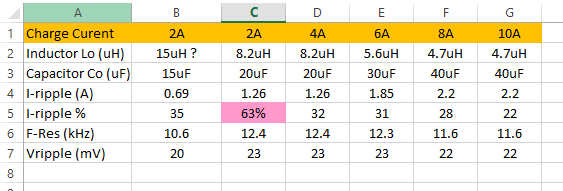
Recommended LC or 8.3uH / 20uF gives a large Ripple current of 1.25A, which is 83% of Iload, much higher than the recommended range in your datasheet of 20-40%

It also is creating unnecessary noise in our delicate circuit (shielded Inductor may help)

It also switches to DCM below 600mA and we have had instability at 150mA.

Can we change LC to  22uH / 8uF or 33uH / 4.7uF  - both of these have resonant frequencies within the required 10-15kHz band.

  • Hi Michael,

       LC is a tradeoff with inductor current rippple and DCR at higher inductances, weighed against increased output voltage ripple when reducing the output capacitance.

    Try changing the inductor to higher value to reduce the inductor current ripple.

    Shielded inductor would help, but revisiting the layout would also help. The key w.r.t noise is to have the input capacitor, HSFET, LSFET loop as tight as possible, with short clean HIDRV/LODRV traces, a short wide PH trace/pour (minimizing ground copper under PH pour along with avoiding routing under high frequency switching node). For noise or excessive ringing, it is recommended to add 0.1uF cap at drain of HSFET, and possibly input and output, as this helps the effective capacitance at a wide range of frequencies.

    DCM is expected behavior of the part at low charge currents, to prevent negative inductor current LSFET will turn off for the period of the duty cycle where inductor current is sensed under the DCM threhold.

  • Yes, we will recheck and tweak our layout further as you suggest.

    But I am trying to understand why TI's Datasheet recommends "inductor ripple is designed in the range of 20%–40% of maximum charging current", (and this indeed appears good practice), but then for 2A, TI recommends 8.2uH (same as for 4A) which gives a 1.25 A ripple and which is 63% of 2A (and 83% of our 1.5A charge current). 15uH and 15uF would make more sense (see table)  

    So, I am interested to distinguish what is a tradeoff for size/cost versus what TI was forced to recommend due to some requirement of the chip freq. compensation (other than the resonant freq).

    I am designing high integrity device and so need to do more than try and see if works.

    For example, If we have no concern about:

    1. size and cost of inductor (DCR<10mOhm) )

    2. Not too concerned about ripple in a battery charging voltage

    How would you recommend we optimize your 2-10A design to operate at 150mA - 1.5A.

    The 20-40% suggests Ir of 300-600mA instead of the 1.25A, using for example 22uH (with 10 uF for Freson. of 10.7kHz) 

    PS: you may think (correctly) - if designing high integrity device, I should get an expert to design my Buck - I did and he told me the above and strongly recommended we use 33uH !

  • Hi Michael,

        You want to design the inductor ripple current at 20%-40% based off of max charge current, to ensure that inductor does not hit its saturation current threshold. As ripple is based off of duty cycle, with would your system's input voltage and output voltage requirements be?

  • Input: 18V

    Output: 14.4V

    I Chrg: 1.5A 

    I Term: 150mA 

    Any help appreciated

  • Hi Michael,

       Using the 33uH inductor will give you < 40% inductor current ripple. If tradeoff with higher DCR and size is not an issue for you, then you can use this configuration with 6.8uH or 10uH capacitor. If you can handle slightly higher ripple then 22uH inductor with 10uF capacitor would also be an option.

    Again this is based off of worst case ripple, assuming 50% duty cycle (9V battery). If your cutoff voltage doesn't allow battery voltage to fall so low, then you can recalculate worst case ripple. 

  • Hi Kedar

    Thanks a lot - this is the confirmation we needed.

    Our test suggests 22uH / 10uF is stable throughougt BQ24630 charge cycle, so problem solved.

    Great service from Texas Instrument.

    Michael