This thread has been locked.

If you have a related question, please click the "Ask a related question" button in the top right corner. The newly created question will be automatically linked to this question.

BQ40Z80: adapt BQ40Z80 for high side current sensing

Part Number: BQ40Z80
Other Parts Discussed in Thread: INA186, , OPA1632

Hi there,

we are evaluating this BMS solution, and are generally very happy with its performance and feature set. Unfortunately, we cannot use low side current sensing because the application has access to the BAT+ power rail only. As this chip would still be the best solution both feature wise as well as price wise, I am looking for a work around with external components. I have just received the EVM of the INA186 current sense amps (25V/V option) to make first tests.

It is my understanding that the BQ40Z80 accepts a differential signal of +/- 100mV at SRP/SRN with a DC bias anywhere between VSS and 0.8 x Vreg, is this correct? I cannot find differential and common mode input resistance of the SRP/SRN pins. And which current do I need to account for? My goal is to translate all voltages using resistive dividers, and to avoid buffer opamps where possible.

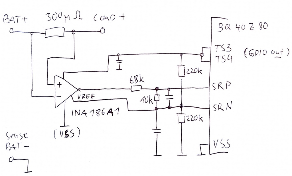
This is a first sketch of the circuit that I have in mind (please excuse the hand drawing). Are there any obvious road blocks that I am not seeing? We will only be using basic protection features like overcurrent and short circuit; no gauging. The BMS will be always kept in sleep mode with reduced current consumption (target: < 100uA total current draw of entire solution), therefore we do not need the current based load/charger detection feature. Battery pack parameters are: 30A discharge, 8A charge, short circuit >= 60A, 6 cells. The resistor values below are chosen such that +/-100A should translate to a differential voltage at SRP/SRN of +/-100mV.

I would also be interested if anyone has done this before. I'll share my results here as well, once I know more about the feasibility of my approach.

Regards

Frank

  • First update: the circuit works, and I do not recognize bias current from SRP/SRN that skews the result noticeably. The zero current reading is low at 65mA, even with this low value sense resistor. Just one caveat: using TS3/4 to supply the amplifier does not work, because setting them to GPIO out HIGH is not persistent. I will need to use a 1.8V LDO instead.

    Still, @TI: please confim if using the SRP/SRN pins at 0.9V DC bias is possible. Otherwise I can easily change the circuit to use e.g. 0.2V bias instead. Absolute minimum would be 0.1V, but I don't want to do that if it is not necessary (although the INA186 spec states that the output works down to VSS + 1mV).

  • Hello Frank,

    The gauge is not designed for this kind of operation, but if you are able to get accurate readings with your application it should be okay if you stay within the voltage range of the coulomb counter ADC.

    I would reference the coulomb counter input voltage in the datasheet, I believe it is a -100mV to +100mV range.

    Sincerely,

    Wyatt Keller

  • You shouldn't exceed the ABS max for SRP and SRN pins, so the gauge doesn't get permanently damaged. Also for accurate readings you shouldn't exceed the recommended operation conditions.

    I think that your Vref should be SRP, not SRN. VSS is SRP.

    What range of currents you're expecting in your application? With that large current sense resistor you may have a lot of power dissipated in the form of heat across the 300mohm sense resistor.

  • Hi Wyatt,

    thanks for responding.

    As long as it sees the correct voltage representation for a given current (along with good enough frequency response, noise, lineary, offset), and I stay within the bias range that it accepts, the BQ40Z80 doesn't know the difference. Needing access both positive and negative power rails may rule out this chip in certain applications, which is also why I wanted to share this because it extends its usability.

    Regards Frank

  • Hi Damian,

    I will make sure not to exceed the abs max of the inputs. The current sense amp will get 1.8V from a LDO, and min Vref is 1.6V, which should guarantee this. In addition to that, the connection is high resistance which should avoid possible latchup.

    Regarding the recommened operations that you mention, does my 0.9V DC bias meet this criteria? I'm asking not only for the gauge ADC, but also for the hardware based overcurrent protection circuit. I am not able to find any information on this in the datasheet. Can you confirm 0.9V bias?

    My other question was about bias current into or out of the SRP/SRN pins. My measurements show that this must be less than 100nA, but also here there is no datasheet info. I need this info to properly calculate the resistor networks.

    Battery pack parameters are: 30A discharge, 8A charge, short circuit >= 60A, 6 cells. This is a 300 micro Ohm shunt. The current sense amp / resistor network has a gain of approximately 3.3, which practically emulates the standard sensivitiy of the BQ40Z80 (1V/A).

    I can swap SRN/SRP if that makes sense. That would only require swapping +/- inputs of the current sense amp as well, no problem.

    Regards Frank

  • Hi Frank,

    Frank Boeh83 said:
    Regarding the recommended operations that you mention, does my 0.9V DC bias meet this criteria? I'm asking not only for the gauge ADC, but also for the hardware based overcurrent protection circuit. I am not able to find any information on this in the datasheet. Can you confirm 0.9V bias?

    The gauge can support the 0.9V, but the issue is the accuracy on the internal current sense circuitry doesn't support 0.9V common mode. The common mode needs to be 0V, which would require a negative supply rail. DC blocking cap won't work in this application. You can look at amplifiers with self generated negative supply using charge pump (TPA613x) or configurable common mode (OPA1632).

  • Hi Damian,

    thanks, this is very helpful. I can also implement 0V bias by providing a small negative VSS to the INA186, but before doing that I would like to have full clarity. Is the problem with the internal current sense that it is actually not implemented differentially, or would a voltage swing of 0~200mV at SRN with a bias voltage of 100mV at SRP work? I can accept reduced accuracy here, as long as full functionality is still given.

    Regards

    Frank

  • Hello Frank,

    The coulomb counter input is pseudo differential. Let me verify and get back to you.

  • Hi Damian,

    thanks for having a look. Just a small addition for clarification: the displayed current readings look good (with 0.9V bias), so the ADC seems to work correctly. My main concern here is: will the hardware based overcurrent protections (charge/discharge overcurrent, short circuit) work correctly with 0.1V or 0.9V bias (i.e. are they [pseudo] differential as well)?

    Cheers, Frank

  • Hello Frank,

    Thanks for the update. The recommendation is that the common mode shouldn't exceed 0.3V, else even if it works well at room it may not work well across temperature and device/process corner cases.

    Let's close this post, but please keep us posted and let us know if you have any other questions by new posts.

  • Hi Damian,

    thanks for confirming, I will then use 0.1V bias to avoid the extra regulator, and do full qualification of the performance. I can accept up to 20% error, because we are only using the overcurrent features. ok to close the thread, many thanks for the good support.

    Cheers, Frank