This thread has been locked.

If you have a related question, please click the "Ask a related question" button in the top right corner. The newly created question will be automatically linked to this question.

TPS92561: LedControl for MachineVision using TPS92561 & TPS92515

Part Number: TPS92561
Other Parts Discussed in Thread: TPS92515

I have following the below mentioned Led control Application for Machine Vision: used TPS92561 and TPS92515 Boost and buck controller.

Link:https://e2e.ti.com/blogs_/b/industrial_strength/archive/2018/05/31/light-that-freezes-motion-insight-into-a-led-lighting-control-design-for-machine-vision?keyMatch=LED%20DRIVER%20FOR%20STROBE&tisearch=Search-EN-everything

As per our requirement, I have updated the schematic, for your reference I have attached same.

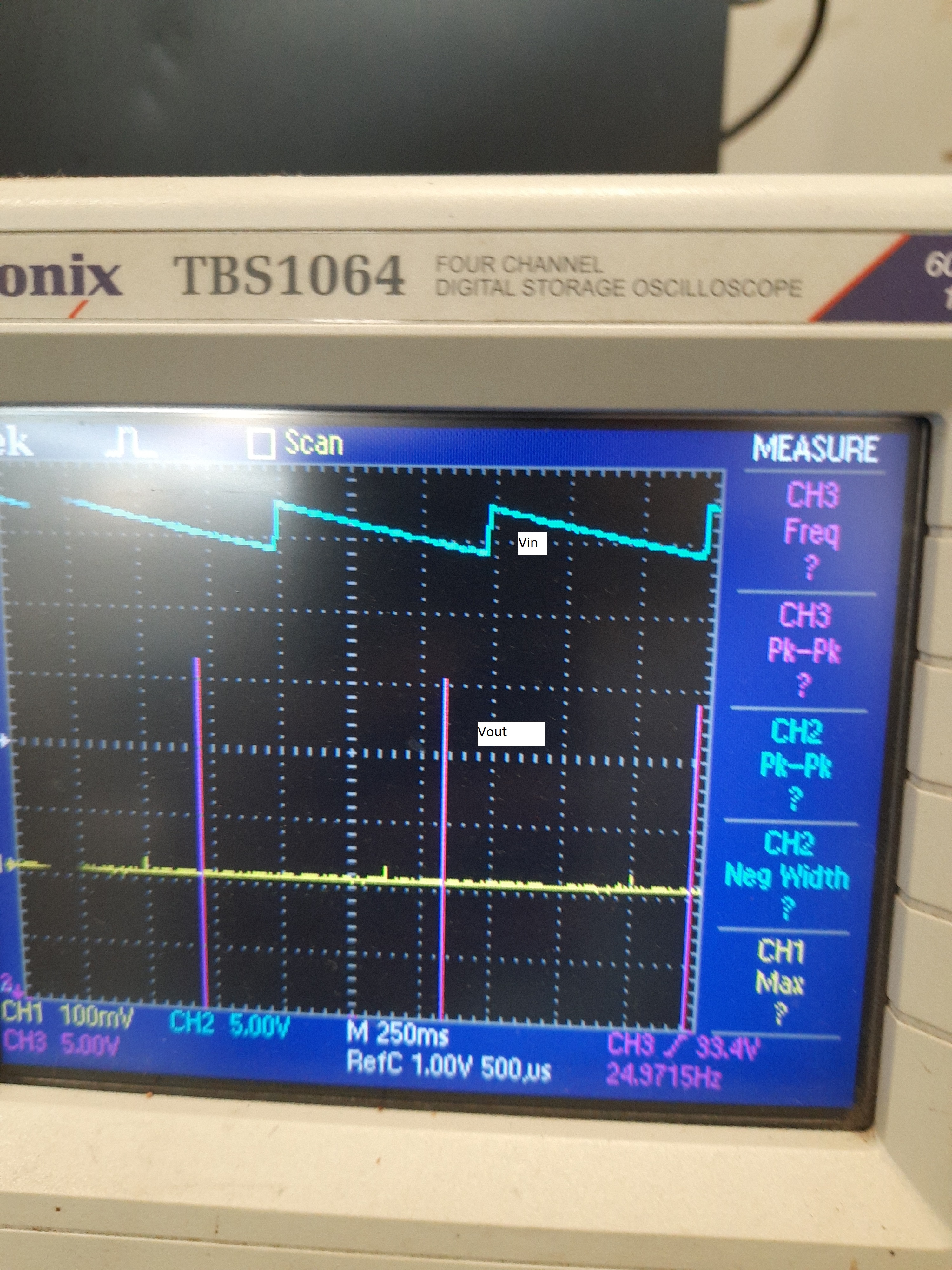
I have faced an issue regarding boost voltage. As per the application note, it should be 48V, but our design it is showing 53V. and Output voltage of TPS92515 IC is 40V in place of 24V.

Also after connecting LEDs, with the trigger on time greater than 500uSec, Buck converter is getting burnt.

I might be missing something obvious.

Any ideas on how to troubleshoot this would be very helpful.

Thank you.

leddrivetps.pdf

  • Hello,

    You have a few things going on here.  The TPS92561 is a current regulator, not a voltage regulator.  It will provide current to the output until it hits OVP which is nominally set to 55V.

    The TPS92515 circuit is incorrect regarding Coff.  The resistor needs to be on the other side of the capacitor.  What you have is the output going right to the capacitor and a resistor to the IC, this will not work.  The If you move C1 connection from the output to the Coff pin is will be correct.  I haven't calculated any of your design yet, best to get it functioning first.  Not sure what you are going to do with the boost.

    Best Regards,

  • Hi Irwin,

    Thanks for your response. You are right, regarding the Coff circuit of TPS92515 IC.

    I will correct it and will do further testing. 

    Actually we are boosting the Led current for minimum ON time.

    Link:https://e2e.ti.com/blogs_/b/industrial_strength/archive/2018/05/31/light-that-freezes-motion-insight-into-a-led-lighting-control-design-for-machine-vision?keyMatch=LED%20DRIVER%20FOR%20STROBE&tisearch=Search-EN-everything

    As per the Link shared above, we are doing the same application, Led Light control for Machine vision.

    Warm Regards,

  • Hi,

    As per suggestion, I have done the changes in the Coff related circuit.

    Now circuit functioning is started.

    Now I am facing the issue related to LED brightness.
    As per the application note, even for small ON time, LEDs are glowing with the set current. (for high current set, high intensity/brightness of leds)

    But I do not get the same result.

    Please guide regarding this issue.

    Warm regards,

  • Hello,

    Have you looked at the output, on command and current?  How long is your on-time?

    Best Regards,

  • I want an ON time from 10uSec to 500mSec.

    At the output, I have connected a LED strip. Not measured a current.

    But as per the application note, my main purpose is that I want high brightness/intensity of LEDs for Low on Time. (10uSec or 100uSec)

    Thanks.

  • Hello,

    What is your input voltage and output voltage?

    I'm not sure what your issue is?  Is it always at full brightness?  Are LEDs glowing?

    I used 38V input and 24V output and rise and fall time of the current for a 100 uH inductor is:

    di/dt rise = 0.14A/us

    di/dt fall = 0.24A/us

    This means for a 10 us pulse the current can get to 1.4A (provide the regulation set point is at least this high), and fall back to zero in 5.8 us.

    How are you measuring circuit operation?

    Best Regards,

  • hi,

    Sorry for the late reply.

    I want an output voltage 24V(but I get 40V at output) with a full current 2.4A.

    As per the application note, we can use a wide input voltage range 8V-36V, I am using 24V as an input.

    Led are glowing but for 10uSec On-time pulse, the led brightness is very low.

    I am not measuring the output current.

    I have connected 16Leds(3V, 700mA) in parallel.

    Warm Regards,

    Vidya

  • Hello Vidya,

    16 Leds in parallel is going to require 3V to drive, are you sure this is how they are connected?  A current regulator regulates current not voltage.  It will drive current until the current level is reached or it doesn't have enough input voltage to do so.  How are your LEDs connected?

    Best Regards,

  • Actually I am overdriving the LEDs, as Led On-time is low.

    Led Connection image as atta ched.

  • Hello,

    Then the output of the TPS92515 cannot be 40V, it must be near 3V.  If 2.4A is going to the LEDs each LED will have approximately 150 mA with about 7.2 watts output power provided you are not running the on-time below 275 ns.  TPS92515 regulates current not voltage.

    Best Regards,

  • Sorry Irwin, for the late reply. 

    My understanding of the Application note is that it will give the 24V fix output with the settable current.(up to 2.4A) even for 10uSec ON time.

    Now I have connected only 2Leds in series instead of 4X4 led matrix. But results are not as expected. Led brightness is very low.

  • Hello,

    The schematic of the LEDs you showed has a 1 X 16 arrangement, 16 LEDs in parallel.  This would be about 3V (depending on the LED used).  If you are actually using a 4 X 4 matrix assuming 3V LED forward voltage the LED arrangement would be about 12V.

    The output of the TPS92515 is not a voltage, it is a current.  It will drive current at the set point of the design and the voltage will end up being what the LEDs determine it will be.

    "My understanding of the Application note is that it will give the 24V fix output with the settable current.(up to 2.4A) even for 10uSec ON time."  No, it won't give a fixed output voltage.  Look at figure 48 on page 53 of the design you are referring to.  As the current is increases you can see the voltage increases.  This is due to the dynamic impedance of the LED string.  If you look at the TPS92515 circuit how can it regulate voltage?  There is no voltage feedback only current feedback.  It does have a settable current.  This operation is similar to taking a lab supply with adjustable current limit driving an LED string.  Set the current to 100 mA then turn the voltage up until the lab supply starts regulating current, 100 mA.  Keep turning the voltage up.  Now when you adjust the current on the lab supply the voltage will be whatever the load lets it be.  You can measure it and see.

    What is the input voltage to the TPS92515 portion of the circuit?  What is Iadj voltage?  Can you look at the switch node of the TPS92515?

    Best Regards,

  • Hi,

    Got your point related to the current regulation of TPS92515.

    The input voltage to the TPS92525 is 55V and the Iadj voltage is 1.8V.

  • Hello,

    If you have 55V at the input of the TPS92515, Iadj at 1.8V I would look at waveforms such as the switch node and if you have a current probe the output current and inductor current.if there is an output capacitor and the output voltage for a start.  The TPS92515 is a fairly straight forward, if the values are correct and the layout is good it should just work.

    Best Regards,

  • Hi,

    I do not have the facility to check current waveforms.

    Here I attached a voltage waveform at switch node of TPS92515IC. Trigger ON Time is 50uSec and Signal Frequency is 25Hz.

    Thanks & Regards,

    Vidya

  • Hello,

    You have multiple channels on the scope.  Can you look at Vin, Vout and the switch node?  Also can you get more than one pulse on the screen and have the amplitude of the signal on the screen?

    Can you also look at the Coff pin and PWM pin?

    Best Regards,

  • Hi,

    Please find the attached images of VIn, SW node, and Vout waveforms.

    There is no signal waveform at COff Pin. PWM is - 50usec On-Time and 40mSec off time

  • Hello,

    If there is no signal at Coff that is your problem.  It should have 1.0V triangle waveform.  Your schematic is wrong as mentioned before, Roff needs to go to the load and Coff is connected to the Coff pin (the resistor is on the wrong side).

    The input to this determines when to turn on the MOSFET.  As Coff charges to 1.0V the MOSFET is turned on, Coff is discharged.  Once the peak current threshold is met  the MOSFET turns off and Coff is allowed to charge again.

    Best Regards,

  • hi,

    Yes, I have corrected the connection at the COff pin as per your suggestion. But for reassurance, I will check the Coff Signal waveform in another card.

    Please what about Sw node and Vout signal waveforms(Attached images)?  Are they okay?

  • Hello,

    If there is no Coff waveform the sw node and Vout will not operate correct  It is rising and current flows but if Coff is not running it cannot work correct.  MOSFET turns on until peak current threshold is met.  It turns off for as long as it takes to charge Coff to 1.0V.  If it doesn't it goes to maximum off-time and you get what you see.

    Best Regards,