This thread has been locked.

If you have a related question, please click the "Ask a related question" button in the top right corner. The newly created question will be automatically linked to this question.

BQ76952: Isolators and ESD diodes placement in the circuit

Part Number: BQ76952

HI,

I have been trying to optimise my schematic by taking references from Datasheet.

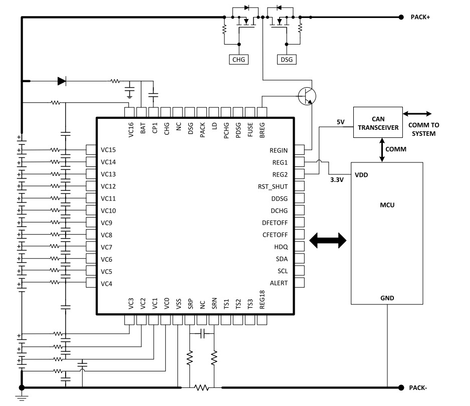
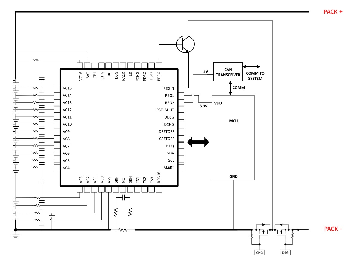
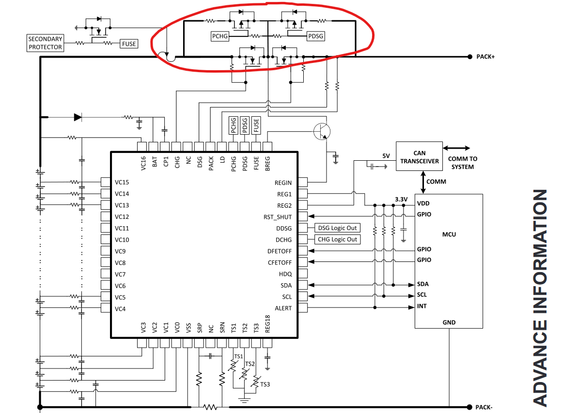
And I would like to ask if it is necessary to use isolation between MCU and AFE communication lines?

Apart from that, should I consider isolating GPIO channels, CAN communication pins or any Voltage level shifters (as I need to do use buck for MCU operation or should I consider flyback converter)?

Regards,

Anurag

  • Hi Anurag,

    It should not be necessary to use isolation between the MCU and AFE. The BQ76952 uses high-side FETs, so if the protection turns off the FETs, there will still be a common ground connection between the MCU and AFE. With low-side FETs, isolation becomes a concern.

    The BQ76952 has 2 LDO outputs that can be used to power an MCU or other circuitry (each provides up to 45mA and can be set to 1.8V, 2.5V, 3.0V, 3.3V, or 5V). You can use other power devices as needed - if you have specific questions on buck or flyback converters, you will need to post a separate E2E question so that the experts for those ICs can help.

    Best regards,

    Matt

  • Hi Matt,

    Thanks for your response.

    I am planning to use FETs on low-side, so it seems I will have to take care of isolation. But, can you please explain little further why do I need isolation with low-side.

    For other questions, I will create new thread.

    Regards,

    Anurag

  • For instance, Datasheet specifies following circuit:

    But, I am trying to connect FETs along low-side as following:

    (Connections Just for reference)

    So, my doubt is:

    1. Do I need to use charge pump circuit with above low-side driving
    2. Are there going to be any issues as you suggested above related to breaking ground connection. Or should I use Isolation?

    Regards,

    Anurag

  • Hi Anurag,

    In some systems isolation may be need when using low-side FETs if the host is outside of the battery pack. For example, if the battery has a problem and the protection FETs switch off, the host (which is using PACK- as ground) may lose communication with the battery monitor (which is using BATT- as ground). In your diagram, the MCU is inside the pack, so this should not be an issue.

    The BQ76952 FET drivers are for high-side FETs. It is possible to use low-side FETs, but you will need to use the DCHG and DDSG signals (instead of the CHG and DSG FET drivers). This would also require a FET driver IC since DCHG and DDSG are digital logic outputs. This image below shows an example My colleague is preparing a detailed report on this specific topic that should be available in one or two months. As you can see, driving low-side FETs with the BQ76952 is a little more complex than using the integrated high-side drivers.

     Best regards,

    Matt

  • Hi Matt,

    This clears my doubts and thanks a lot for sharing this diagram, highly appreciate it.

    Regards,

    Anurag

  • Hi Matt,

    One more thing which I missed is how can I use PCHG and PDSG with low-side FETs.

    As your suggestion, I can shift CHG and DSG to DCHG and DDSG pins.

    For reference check out Figure 20 in 8.2 Typical Application section in datasheet.

    As attached here:

    Regards,

    Anurag

  • Hi Anurag,

    Yes, level shift the PCHG and PDSG from the battery voltage.  Use low side N-ch FETs with resistors across the appropriate power FET.  Use zeners on the gates and dropping resistors as needed.

  • HI ,

    Thanks for the response.

    As stated in the datasheet Voltage on PCHG and PDSG will be typically 8V7 and max 9V7 for Vpack>=8V.

    So, I need to shift it to appropriate voltage levels which can operate N-ch FETs.

    Regards,

    Anurag