This thread has been locked.

If you have a related question, please click the "Ask a related question" button in the top right corner. The newly created question will be automatically linked to this question.

TPS54824: TPS54824

Part Number: TPS54824

Hi, 

In our current design we want to provision the VDDMIN, VDMMAX quick switch for easier testing as below:

Hence we have made changes in schematics for the same in the below schematics snapshot:

Our query is :

Is it possible to leave the jumper like below so that switching between VDDMIN and VDDMAX while the drive is hot is possible.  The jumpers like the way it is now, will there be any design issue or issue in the output voltage. Kindly confirm.

Regards,

Ranjana

  • Hi Ranjana,

    The images in your post didn't come through properly. Can you try to post them again?

    Will these be hardware jumpers that someone populates on a header? I wouldn't be concerned about the DC/DC but the output voltage may move back and forth due to glitches when manually populating the jumper. To help limit these glitches, you would want some filtering between the jumper and the FB network of the TPS54824. However the filtering should be chosen carefully as connecting up filtering to the FB pin of the TPS54824 could affect the loop.

    Anthony

  • Hi Anthony,

    Please find the  TPS54824 VCC 3.pdf schematics page attached.

    Regards,

    Ranjana

  • Hi Ranjana,

    I would not recommend that implementation because if both jumpers are accidentally left open, the FB pin would be shorted to ground through the bottom resistor and in response the TPS54824 will bring the output voltage near Vin. The TPS54824 IC should be able to handle this but I think that might damage whatever it is powering.

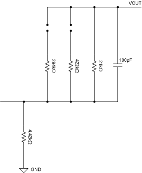
    An implementation like the image below could work. This way there is always an upper resistor in the FB divider.

    • With both jumpers open, the top resistor is just the 21kΩ giving +5% (based on the comments in the schematic)
    • With the middle jumper populated the top resistor is 21kΩ||422kΩ which gives ~20kΩ and the 0% voltage
    • With the left jumper populated the top resistor is 21kΩ||294kΩ giving ~19.6kΩ and -5% voltage

    Let me know if you have any question on this.