A related question is a question created from another question. When the related question is created, it will be automatically linked to the original question.
If you have a related question, please click the "Ask a related question" button in the top right corner. The newly created question will be automatically linked to this question.
Thank you for your interest in the UCC28780 ACF controller.
The schematic diagram you provided is blurry and it is difficult to read many of the parameters. However, the output states 5V/10A and the secondary to auxiliary turns ratio is 2:4 which puts ~10V on the VDD_pri rail on the primary side.
This voltage is not high enough to sustain operation. I recommend a 1:3 ratio to obtain at least 15V on VDD_pri.
I recommend that you use the UCC28780 Excel design tool to calculate the parameters for this design, and also for the 5V/20A design. https://www.ti.com/lit/zip/sluc664 The tool provides inductance and turns ratios, but cannot provide actual turns for each winding, because that depends on the core size that you choose. Most designers select the core shape and size based on their specific packaging requirements, so we cannot anticipate all of the wide variety of choices in the tool.
Since the schematic shows Silicon MOSFETs on the primary side, I recommend that the UCC24612-2 SR controller be used, which has timing better suited for a Si power stage. The schematic appears to list the UCC24612-1 device which is better suited for a GaN-based power stage.
Ulrich has pointed out that the transformer Aux winding turns is not enough to put VDD voltage higher than 10V VDD_OFF . the issue you faced was tested on original transformer or you had changed the turn ratios ?
BTW: For a 5V/10A output , Both Npsa =16:2:4 and 16:1:3 are not a good choice , I recommend you start at 32:2:6.
There is a application note can help you to debug the start up issues , please follow the AN to check what happens on your board if other protections occur.
Replace the transformer on UCC28780EVM-021 EVK with Npsa=32:2:6 & Lp=110uH, connect the VDD of the UCC24612 on the secondary side to the 5V output, and R24 &R26=100K, but the 5V output voltage is unstable, could you help to check it. thanks
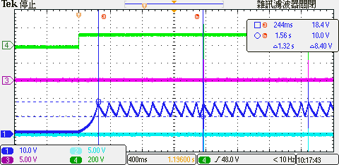
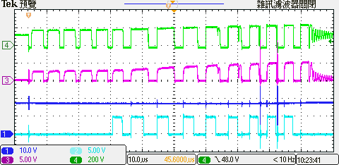
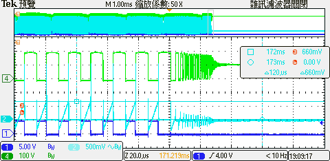
Attach the operation waveform of the primary side CH1: Vdd_pri CH2: PWML CH3: VS CH4: Vswn1
The start-up problem you are having is from an over-voltage protection (OVP) shutdown. This type of fault will automatically retry after a delay of about 1.5s as can be seen in the first screen-shot.
The increasing VS peak voltage indicates OVP when it reaches the 4.5V OVP threshold. The cause of the start-up OVP is an open-loop feedback path.
Changing only the transformer and R24 &R26 is insufficient for proper function of the revised EVM. The ATL431 biasing components are sized for a 20V output and these do not provide enough current to the shunt regulator when operating from only 5V.
Specifically, R11 and R13 also need to be reduced to provide sufficient current to operate the shunt regulator U2 and the opto-coupler U1. A quick estimate would be to divide their values by a factor of 4: hence R13 becomes ~8.2K and R11 becomes ~2.7K.
That should solve the static biasing and regulation issue, but then the dynamic compensation values for C22 R8, C27, C28 and R27 will also need to be adjusted for the new regulation level and transient response. These are not as simple to estimate so I recommend to use Excel Design tool to determine the recommended values.
Your schematic diagram closely matches that of the EVM, but the copy of the tool you used has different values than on the board. Also some of the user-selected values are far from the recommended values.
For example, the tool recommends 0.18ohm for the current-sense resistance, whereas the board shows 0.227R (at R18-21). The higher R-value will prevent you from achieving full power.
The SR controller U3 can be biased from the 5-V output, however the gate-drive will not be strong for the high output current involved and the SR FET will not be as efficient as you might expect it to be. Figure 15 of the UCC24612 datasheet shows another way to bias it for stronger gate drive, if an auxiliary winding is not used.
Note: in the waveforms shown above, CH2 is PWMH, not PWML.
Thank you for your reply, I will try to adjust as soon as possible to confirm whether it can be started normally Are there any recommended values for C22, R8, C27, C28, R27? thanks
When the Excel calculator tool is fully filled out, C22, R8 and C28 values are generated by the tool (Cdiff, Rdiff, and Cint). R27 is not programmed in at this time. I suggest to keep it at zero (0R) until normal switching operation is achieved, then fine tune later. I think you can keep C27 = 3.3pF for now, and fine tune later after normal operation is achieved.
After filling out the Excel calculator and refer the calculation results, replace part value is R29=56K, R14=20K, R18~21=0.18R, RDM=150K, R11=2.7K, R13=8.3K, but the output voltage is still unstable. Please help to check the problem. thanks
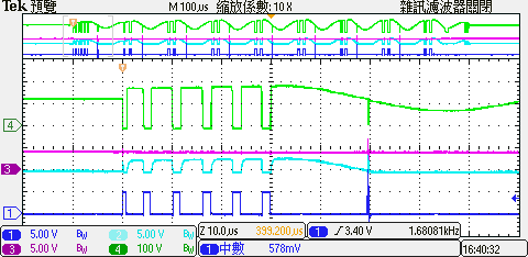
Attach the operation waveform of the primary side CH1: PWML CH2: VS CH3: FB CH4: Vsw(Q4 Drain)
From the green waveform (Vsw), it looks like the high side MOSFET (Q3?) is staying on too long and allowing all the charge in the clamp capacitors to ring out. Please check the PWMH signal. If it is high for almost 100us, then check the value of the RDM resistor. It may be incorrect.
In a situation, put the oscilloscope probe on the VS pin, the output can be stable, but after removing the probe from the VS pin, the output unstable. What should I pay attention to?
The UCC28780 controller senses the dv/dt of the AUX waveform at the VS input to determine the timing of the PWML and PWMH signals. Normally, the VS pin should not have any capacitance introduced on it because capacitance to GND will slow down the dv/dt and distort the timing.
In your case adding the oscilloscope probe adds capacitance to GND and improves operation. This suggests to me that there is excessive capacitance from VS to Vaux (across the upper VS divider resistor). Adding some capacitance to GND tends to cancel out the upper capacitance.
I suggest to place a small SMD capacitor, maybe 2~3pF, from VS to GND and see if operation becomes more stable. If only a little better, add a little more cap. A typical probe these days has about 8~12pF of capacitance which is a lot. I don't recommend adding that much to VS, but you did get an improvement with the probe, so it can't be ignored.
If a few pF cap to GND solves the stability issue, then continue to debug your prototype further. However I recommend to re-layout the pcb to minimize all capacitance on VS. Follow the pcb layout guidelines and recommendations in the datasheet closely. Not only for VS but for the other pins, too.
I have encountered a few problems, please help thanks
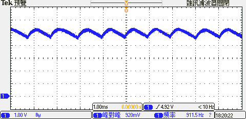
1. When the load is 0A, the output voltage is too high, need to add about 10mA load, the output will be stable at 5V, the transformer setting Npsa=32:2:5 & Lp=110uH. 2. The output has a low frequency of 1KHz, and it is not improved after adjusting C22 & R8, see attached Fig1 & Fig2. 3. When the output current more than 2.4A, the protection will be activated and reset within 1.5 seconds, CS & VS found no abnormalities, see attached Fig3.