This thread has been locked.

If you have a related question, please click the "Ask a related question" button in the top right corner. The newly created question will be automatically linked to this question.

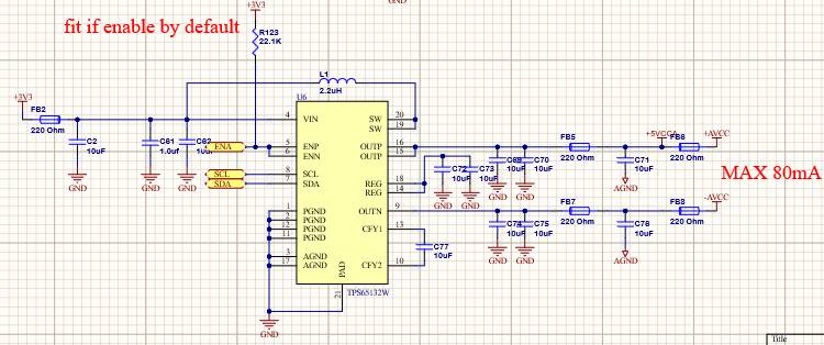
TPS65132: I2C read issues (possible errata?) and can't set current to 80mA.

Part Number: TPS65132

Hi, hope you can urgently help... we simply cannot read data back from the TPS65132W part and suspect some errata. 

Question 1: Please help why I2C read is not working? Maybe we have older silicon so any errata and chip ID's would help?

Question 2: Since I2C write does work then why can we not seem to get 80mA from VNEG rail? The VNEG rail does not come up?

Information:

I've read a few posts in this forum of others complaining about the same issue with this part.

All values read back over I2C as ZERO. 

*Note values are WRITTEN - we observing the changing in rail voltage on writes to reg 0 and 1, however READ does not work.

We are following exactly as per data sheet (see wave forms attached).

>Vin is 4.5V (above UVLO). ENN and EN are tied together and driven low then high (3.3V) by HOST before I2C access attempt.

>Load on each + and - rail is ~60mA (so we are attempting to set the APPS pit to 80mA - this seems not to work).

>Tried from 50kz up to 400khz I2C rate.

>Tried read from EEPROM and internal DAC Regs but still zero.

>I2C write to reg 0 and 1 change voltage levels. 

TPS_REGWRITE(TPS65132_CONTROL_REG, 1); //EEPROM READ
TPS_REGREAD(0, dta); //Read any reg 0 to 3 - Always returns ZERO


TPS_REGWRITE(TPS65132_CONTROL_REG, 0); //DAC READ
TPS_REGREAD(1, dta); //Read any reg 0 to 3 - Always returns ZERO

The waveform 

  • Hello,

    We will review your post and get back to you with any feedback in the next couple of days.

    Kind Regards,

    Liaqat

  • Hello Anika,

    There is no errata and there is only one version of silicon under this part number which has been sold in millions so I am sure that there is no issues with the device itself in general but let's try to debug what you are seeing.

    When you first power up without writing or reading anything from TPS65132W device, what voltages do the positive and negative rails come up to?

    You mentioned that negative rail does not come up. Does this mean voltage of zero volt or some other voltage is present on the negative rail? What if you disconnect the load and there is zero load on both positive and negative rails, does the negative rail come up in this case? What is the voltage in this case?

    Even without setting the APPS bit to 80mA mode, the negative rail should still come up to some voltage even if there is over load condition of 60mA on it. So I m trying to figure out why the rail is not coming up at all.

    Although schematics for this application is very simple, can you please still attach the schematics so that I can quickly review just to ensure that there is no issue schematically.

    As for reading I2C register, is it possible that all eeprom registers are somehow already set to 0x00 in the devices you have? When you change the voltage on the positive rail using I2C command, can you please capture that I2C write sequence and than also capture I2C read-back sequence of the same register (register 0x00) without doing any other I2C transaction in between the two operations?

    Let's debug this further based on the answer to above questions.

    Kind Regards,

    Liaqat

  • Thanks Liaqat,

    Great to hear about the errata.

    Fresh chip comes up with +5.4V on the VPOS rail. The negative comes up at -1.2V when using 100ohm test load to gnd - with circuit connected its even lower but I dont have exact measurement for it.

    Here are some test results:

    >Having zero load the VNEG rail comes up to the desired voltage.

    >Having 100ohm load (main circuit detached) on VNEG the rail comes to ~ -1.2V.  

    >I2C commands can be written to the device and rails respond. Re-power the board the settings retain so EEPROM write seems to work.

    >Having 100ohm load on VNEG the rail and writing 1 to APPS reg the rail comes to ~ -2.5V.  

    >I2C read commands always respond zero regardless.

    >Same condition on multiple boards.

    >Tried 3.3uF and 10uF for flyback. 2.2uH is recommended 1269 part from datasheet.

    Attached schematics hope you can view.

    Please let me know your thoughts on this.

  • Hello Anika,

    Thank you for posting the schematics and the answers to my other questions. I reviewed the schematics and it looks good. Only modification I was going to possibly suggest is to reduce C77 to 4.7uF but it appears that you have already tried out few different values for this capacitor.

    Also, please note that TPS65132W comes factory programmed with 80mA mode as default so there is no need to program it in your application.

    I did not see any pull up resistors on the I2C bus but since I2C write is working, I assume resistors are located somewhere else on this bus. What is the value of these pull up resistors?

    Although I don't see why this should be a problem, you are using 2x10uF as output capacitance for negative rail whereas EVM uses 1x10uF. As an experiment, can I suggest to use just 1x10uF to see if it changes the behavior in any way?

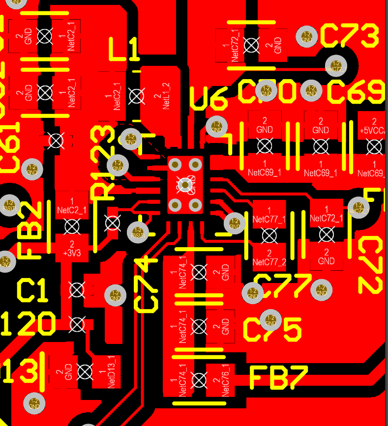
    Frankly, I do not see any problem schematically, so my only guess is either defective parts or some other board related assembly issue.

    Kind Regards,

    Liaqat

  • Hi, I tried experiment with capacitive loads on the outputs and there is no change in VNEG. It's strange that same exact same behavior on both our sample boards. 

    Would you mind checking the date codes on the part to see if anything rings alarm bells? Marking on chip below:

    65132YA 

    TI 9CI

    A45R

    This one has me stumped as the PCB layout is pretty straight forward also...

    You can see by the I2C plots that the rise time of I2C is pretty good - we are using 4K7.

    Also please will you enable Sample Order on my account so I can order some samples though TI samples page (it is currently rejecting me)?

    THANKS!!


  • Hello Anika,

    Since you mentioned wearlier that with zero load, VNEG comes up at proper voltage, I am thinking that the FB7 and FB8 may not really have zero resistance at DC may be causing an excessive voltage drop across them. Can you doucble check the voltge before FB7 on the negative rail?

    Unfortunately, I will not be able to provide lot trace code or enable samples for you. You will need to contact local TI sales office for that.

    To make further debug easier, you may also consider ordering an EVM of this device at:

    Kind Regards,

    Liaqat


  • Yes well all the testing with 100Ohm load on VNEG is without FB7 fitted and with the load across the output cap/s.

    I think there is only two options; we've got defective parts from the supplier or there is some hardware issue.

    Sorry to hear that you cant support us with samples.

  • Hello Anika,

    Yes,  I think we have already tried what I though could be the issue so you are likely correct about the either defective devices or a board assembly issue of some sort. Since I have no other suggestions at this time, I am closing this thread. Please feel free to open another thread if there are any further questions.

    Kind Regards,

    Liaqat

  • Hi Liaqat, I've purchased the EVM and the issue happens on the EVK also so there is some issue with the silicon. 

    EVM Testing:

    Simple 100Ohm load on VNEG and VPOS (~50mA load). My power supply is bench-top 1.3A 5V.

    No matter what setting (80mA or 40mA) is in RAM or EEPROM, or what order I enable each +/- rail the VNEG rail never gets past -2.5V. 

  • Hi,

    Unfortunately the EVM has the exact same issue.

    Please are you able to test this yourself on the EVK with 100Ohm loads fixed to VNEG and VPOS you should see what we mean?

    With benchtop supply set to over 1A @5V and 100ohm loads on VNEG and VPOS no matter what the EEPROM and RAM settings the VNEG rail only makes it to about -2.5V.

    *Note: if we completely disconnect load then PWR up the board the -5.4V comes alive and THEN when we connect 100ohm load it stays at -5.4V and draws appropriate load current (obviously unacceptable in real-world)

    Perhaps some startup issue with the VNEG rail. 

    Please help some secret register setting related to startup timing? Or load setting?

    Thanks!

  • Hello Anika,

    Thank you for the update. I will be able to look into this on an EVM on Monday Sep. 28 and will update you then.

    Kind Regards,

    Liaqat

  • Hello Anika,

    Thank you for your patience. From your latest description of the problem (*Note: if we completely disconnect load then PWR up the board the -5.4V comes alive and THEN when we connect 100ohm load it stays at -5.4V and draws appropriate load current) and from my testing on an EVM, I think that I understand what is going on. Basically, TPS65132W has a current limit in the soft-start phase of the startup which limits the current to approx. 25mA for TPS65132W during startup. I copy the relevant description below from the datasheet section 8.3.5.2

    ===================

    The CPN integrates a soft-start that slowly ramps up its output voltage VNEG within a time defined by the selected mode (40mA or 80mA), the output voltage and the output capacitor value. For TPS65132Ax and TPS65132Bx(except TPS65132B2), the startup current charging the output capacitor in 40mA mode is 50 mA, and 100 mA typically in 80mA mode. For TPS65132B2, TPS65132Lx, TPS65132Tx, and TPS65132Wx, the typical ramp-up times are slowed down by a factor of 4 (i.e 12.5 mA and 25 mA typical output current for 40mA and 80mA modes respectively) and the inrush current is also reduced by a factor of about 4.

    ===================

    Full current of negative charge pump  is only enabled after the soft start phase where output capacitors have been charged and negative rail has reached its regulation level. As explained in the datasheet description I copied above, some of the other devices in the TPS65132 family (such as TPX65132Ax, TPS65132Bx) have higher soft-start current limit than TPS65132W.

    So what you are observing is expected behavior of the device.

    Kind Regards,

    Liaqat

  • Hi Liaqat, wow that's burred in there and a very odd design that the specified device output current can't be practically used unless the load can be controlled during power-up. Essentially this makes the part unusable for most applications at 80mA. Seems like we have over a thousand dollars of junk proto boards now because the only part that is a QFN seems to be the W variant. 

    Not great.

  • Hello Anika,

    I am sorry about your proto board situation but "W" version of this device is specifically designed to lower the inrush current by having a smaller soft start current limit. Since we have at lest concluded what is causing the issue that you were observing, I closing this thread. Please feel free to open a new thread if there are any other questions.

    Kind Regards,

    Liaqat