


According to SLVA811A–December 2016–Revised June 2017, page 14, Figure 16. 24-V Source Follower MUXing Circuit Using Two TPS26600s
Hi friends, pls check attached pdf, if the images aren't shown
Anybody can confirm If this example only works for OVP like 33VDC for the auxiliary TPS2660, because OVP would be tied to ground through R5 (100K) when:
- dVdT (main TPS2660)= 0V
- source follower mosfet = 0V
If my assumptions are correct, the device will use the default factory OVP = 33V because does'nt exist a voltage divider in OVP (Is correct?)
BTW, I'm requiring a priority muxing design with TPS26600 with:
UVset = 10VDC
OVset = 55VDC
here the value from TPS26600 Design calculator tool:
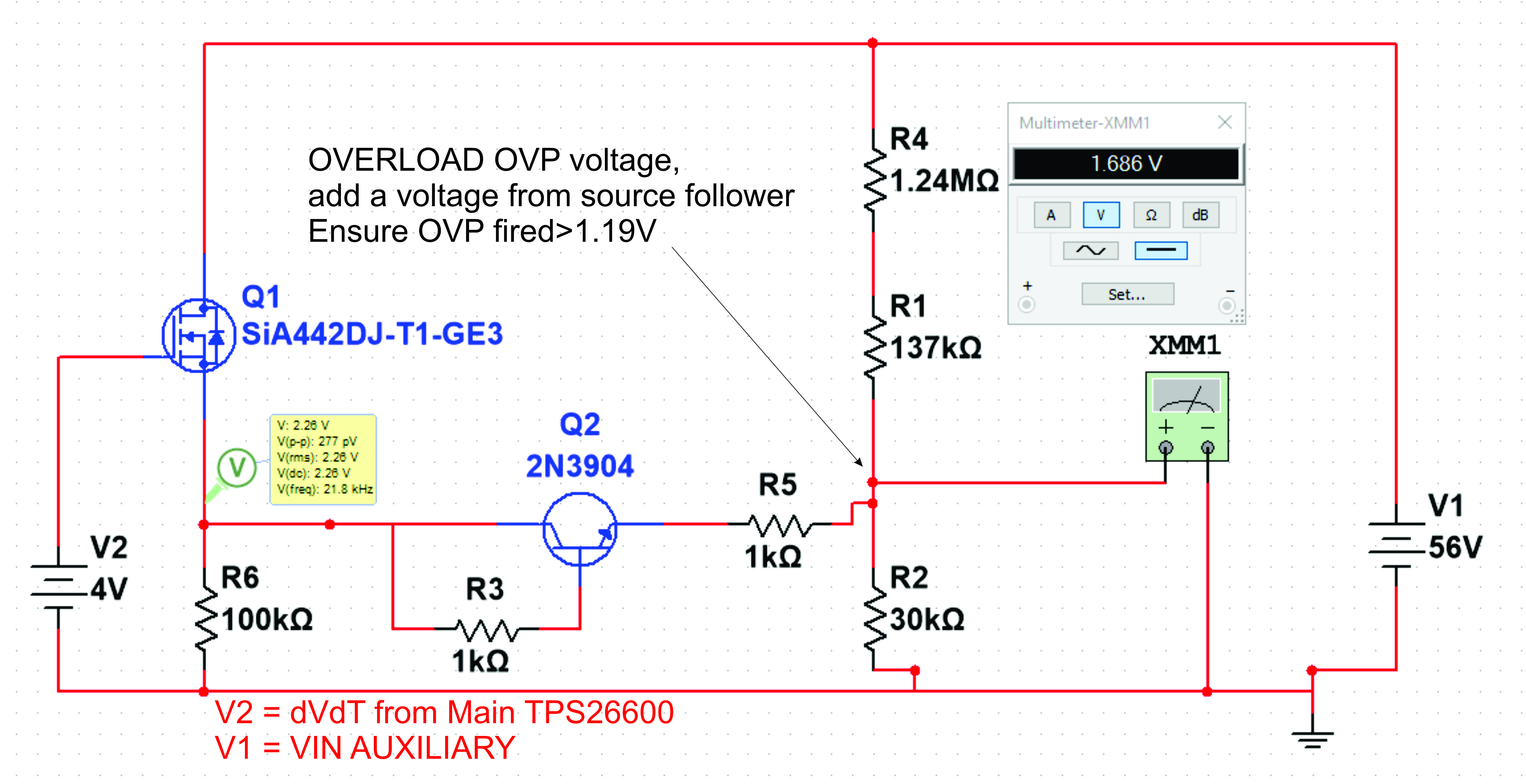
If I followed this same scheme of priority muxing but without losing "OVset" = 55V in auxiliary TPS, then I'll place a simple "voltage adder" + NPN transistor:
With this I have:
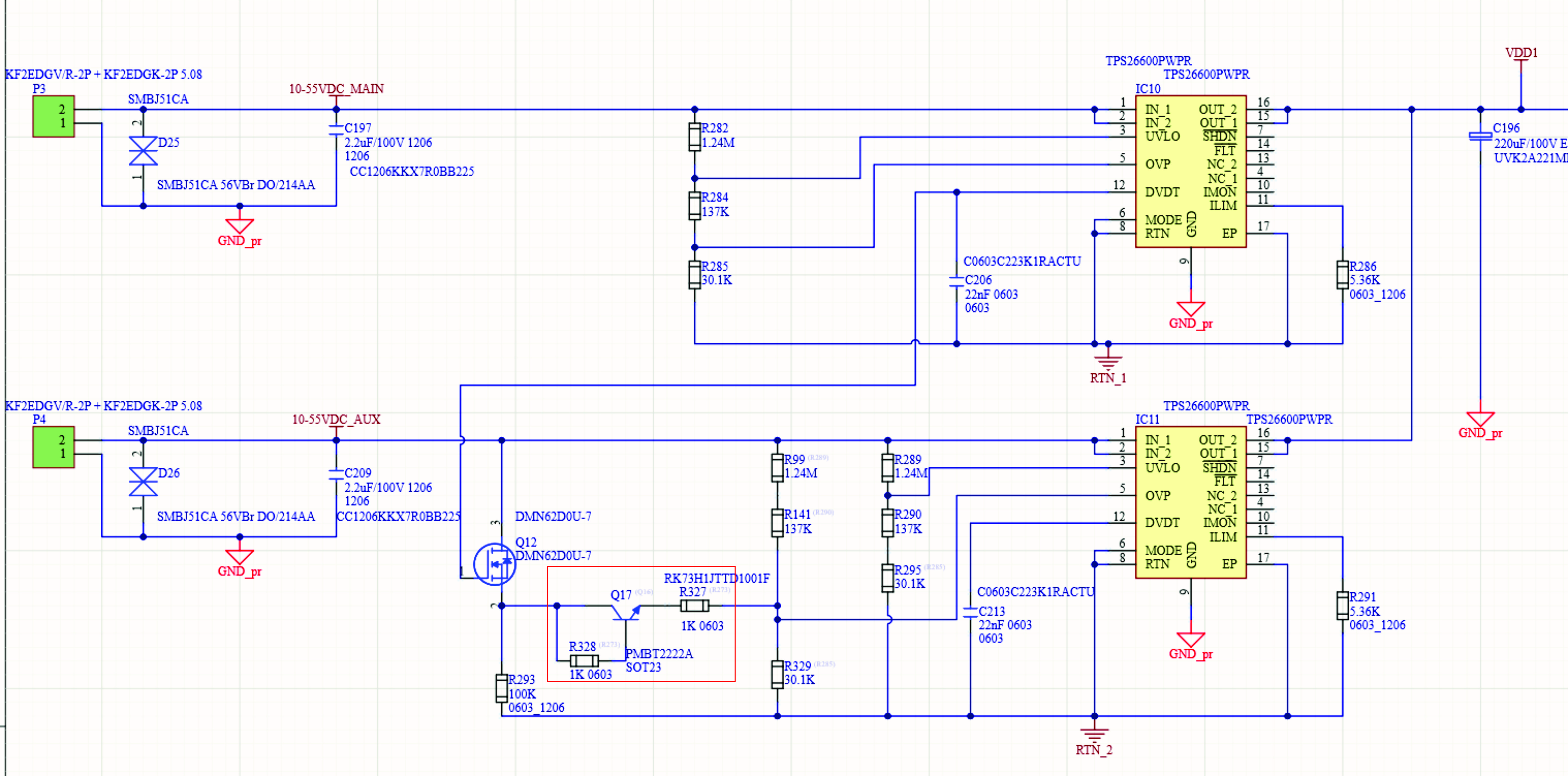
1) if dVdT_main = 0V ( Switch to Aux )
NPN turn off, R327=1K left floating, and R99+R141, R329 work to give the OVPset = 55VDC as expected
2) if dVdT_main = 4V ( UVset< Main voltage < OVset) Main have the priority
NPN turn on, and add a voltage to "OVP auxiliary", forcing OVP > 1.19V (Overvoltage threshold voltage) turning off internal mosfet
- Please anybody can help if my design can work as simulation?
- My calcutation are corrects?
- Why all examples will TPS series never use shutdown pin to switch priority? Is there any disavantages, slow time transition?
Thank you very much in advance
Question is:
My design wor