This thread has been locked.

If you have a related question, please click the "Ask a related question" button in the top right corner. The newly created question will be automatically linked to this question.

TPS61023: TPS61023 Output current

Part Number: TPS61023
Other Parts Discussed in Thread: DRV8837, TPS61020, TPS62802, TPS63802

Hallo,

I am using TPS61023 to control motor using DRV8837. TPS61023 parameters: Vin=3V, Vout=3.3V, max. output current for motor=700mA

But the device resets sometimes when the motor is turned ON.

Is there any changes required in the design? What is the max.output current of TPS61023 when Vin is 3V?

I am using 1uH inductor (74479787210B) for TPS61023. Is it fine? or are resets because of need of higher value capacitors?

Thanks in advance

  • Hi Jain,

    The chosen inductor saturation current level is only 1.15A. Please change to a higher Isat inductor and try again.

    TPS61023 switch valley current limit minimum spec is 2.7A. For 3Vin-3.3Vout application, the estimated maximum output current is around 2A.

  • Hello,

    But my application requires max. 700mA. Does TPS61023 still require higher inductor saturation current?

  • Hi Jain,

    700mA is the output current. You need to calculate the inductor peak current, then a suitable inductor could be selected.

  • Hello,

    Thanks. I have replaced the inductor with a higher saturation current.

    I have connected now a second boost converter TPS61020 which has output voltage of 3V (VCC) which supplies power to microcontroller as it has regulator mode and then TPS61023 for motor-Vcc (3.3V). There is a voltage drop at VCC whenever the motor is ON and it leads to reset.

    What should be the delay for soft startup for both the converters?   Currently, I have 5ms delay after TPS61020 Enable high and then again 5ms delay after TPS61023 Enable high.

    Or is there any other solution which avoids resets or voltage drop?

    Thanks

  • Hi Jain,

    TPS61020 typical start up time is around 4ms and TPS61023 startup time is around 1ms. It's better to wait for the device finished startup time then apply a load to VCC, So I think you have to keep the 5ms delay time. 

  • Hello,

    but even with 5ms delay for both the converters, the device resets.

    What is the max. output current for TPS61020 at Vin=2.8V & Vin=3V and Vout=3V?

  • Hi Jain,

    Per datasheet, the maximum output current at Vin=2.8V, Vout=3.3V is around 1A. The maximum output current at Vin=3V, Vout=3.3V is around 1.1A.

  • Hello,

    I am still having issues of resets when motor is turned ON using both boost converters.

    I have noticed that when TPS61020 is turned OFF during motor operation i.e current is supplied directly from pass-transistor T105 to TPS61023 then it works fine 

    OR when TPS61020 output is connected directly to DRV8837 motor bridge then also it works fine.

    There seems to be problem when I have both boost converter active for motor operation.

    Is there any mistake or changes required in schematic? I need max. 600mA output current for motor operation.

    Thanks


  • Hi Jani,

    Could you capture the waveform of VCC_BAT, VCC, MOTOR_VCC nets waveform when Motor is on? I need to check the waveform first and see what's the voltage drop of TPS61020. 

    BTW, you mentioned TPS61020 output 3V to supply microcontroller. Do you know how much current will the microcontroller draw during working? And are you sure the motor driver DRV8837 is drawing 600mA from MOTOR_VCC? I mean is there a huge inrush current when motor is turned on. If the inrush current is high, the TPS61020 output voltage will drop quickly and cause the reset. So it's better to capture the three net voltage and motor driver inrush current waveform.  

  • Hello,

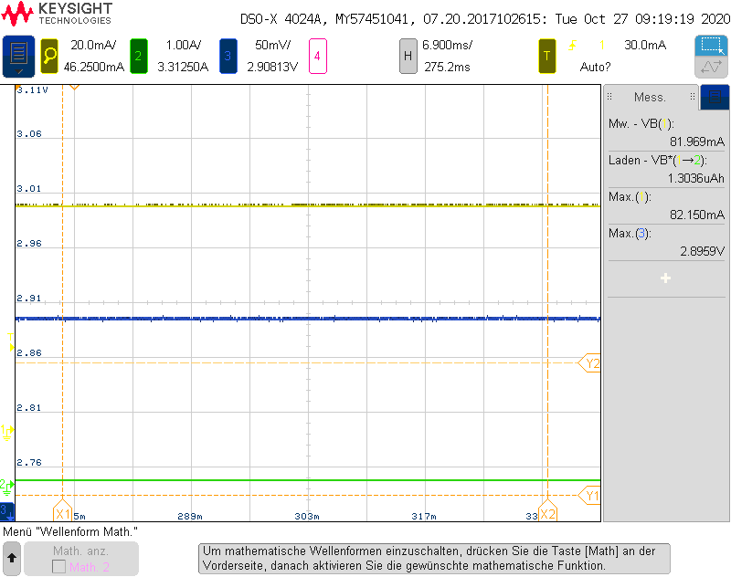
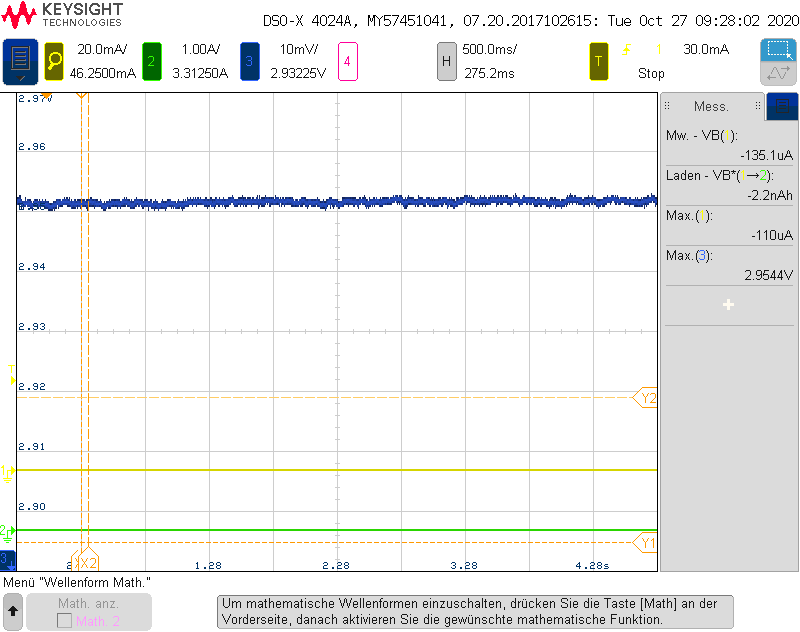
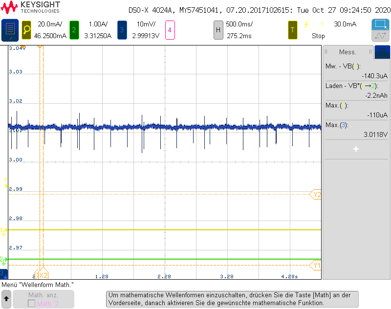
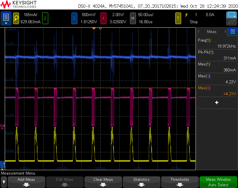
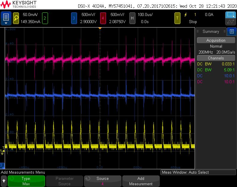
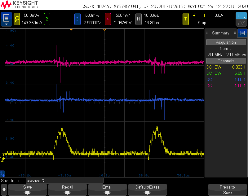
    Blue w/f - VCC_BAT (3.2V)

    Pink w/f - VCC (3V)

    Green w/f - Motor_VCC (3.3V)

    The waveform below had TPS61020 OFF and VCC directly from transistor. Here we see, there is a small spike in Motor_VCC after motor is OFF.

    In below w/f there was no reset and both boost converters are active.

    In w/f below, reset occurs and there is spike at Motor_VCC.

  • Hi Jain

    Jusr let you know taht Zack is out of office. Please allow us reply next week. Thanks for your kind understanding.

  • Hi Jani,

    Sorry for the late reply. I just come back to office from vacation.

    1. For the first waveform, if I understand correctly, the MCU send enable high signal to TPS61023 at time 1 so TPS61023 output voltage (green line) rise up to 3.3V. At time 2, the motor is off, the spike at MOTOR_VCC is a normal behavior which is same with load transient overshoot. You don't need to worry about it.

    2. The second picture looks good. What's the setup different between w/f 2 and w/f 3? Is the reset happening with a small probabilty?

    3. For w/f 3, why the MOTOR_VCC rise to so high? In your previous post, you said the reset happens when there is a voltage drop at VCC whenever the motor is ON and it leads to reset. But this waveform shows VCC voltage is quite steady.

  • Hello,

    w/f 2 &3 have same setup. Firmware development team have changed code and now there is no drop at VCC when both converters are active.

    Reset occurs quite often when both converters are active and during which I notice spike in MOTOR_VCC. Probably the spike in MOTOR_VCC resets the device but I am not sure what leads to this spike of more than 6V. 

    Could it be that TPS61023 is in power save mode and sometimes it doesn't supply enough current to DRV8837 which results in reset?

    or the series connection of the 2 boost converters result issues?

    The device works fine when I turn-off TPS61020 during motor operation and current is supplied directly from transistor as in w/f 1. This achieves the result but i think it is not a right solution to the problem.

  • Hi Jani,

    1. Reset occurs quite often when both converters are active and during which I notice spike in MOTOR_VCC. Probably the spike in MOTOR_VCC resets the device but I am not sure what leads to this spike of more than 6V. 

    Which kind of spike do you mean here? Do you mean when motor is off, MOTOR_VCC will rise? 

    2. Could it be that TPS61023 is in power save mode and sometimes it doesn't supply enough current to DRV8837 which results in reset?

    TPS61023 works in power save mode at light load condition and pwm mode at heavy load. When load current is high, it will enter into pwm mode.

    3. I would suggest you provide me the waveform of either VCC or MOTOR_VCC drop waveform. So that I can find the root cause.

  • Hi,

    Ble w/f- Vbat, Purple w/f - VCC & Green w/f - Motor_VCC for Vout = 3V (TPS61020)

    I have noticed now that when Vbat > 3V i.e in this case Vbat =3.1V, there is voltage drop at VCC and when Vbat <=3V then there is no voltage drop at VCC

    In below w/f the Vbat=3.1V

    in below w/f Vin=2.9V & there is no drop at VCC

    whenever reset occurs there is huge spike at MOTOR_VCC of approx. 6V as shown in w/f 3 above. I am not sure why it is so high beacuse output of TPS61023 is 3.3V.

  • Hi Jani,

    From the waveform 1, TPS61020 voltage drop is quite high when TPS61023 startup. Now the Vbat is 3.1V, which is higher than TPS61020 output VCC. TPS61020 has down regulation function. If the input voltage reaches or exceeds the output voltage, the converter changes to the conversion mode. In this mode, the control circuit changes the behavior of the rectifying PMOS. It sets the voltage drop across the PMOS as high as needed to regulate the output voltage. But the load transient performance is bad at down regulation mode. That's why you see a bigger voltage drop.

    Do you really need the down regulation feature? Is it possible to change TPS61020 to TPS61023?

    I didn't see waveform 3.

  • Hello,

    I am using 3V lithium battery for the application and when the battery is new then battery voltage is approx. 3.3V. Therefore, i need regulation mode if voltage is more than 3V.

    I have changed the design with TPS61023 input connected to the battery voltage instead of VCC. So, now both boost converters are in parallel instead of series connection. Is this a better solution to this problem?


  • Hi Jani,

    If you need a 3V voltage from the battery, you could select a TI buck-boost converter to output a fixed 3V voltage to supply mcu.

    Changing the TPS61023 input from VCC to battery voltage is one solution because the TPS61023 power will draw from battery. VCC load current is really small so the voltage drop won't be so high.

  • Hello Zack,

    I have tried the above method but component TPS61020 is getting defect such that few PCBs are consuming around 250mA in standby mode and few PCBs are consuming 15mA . When I had PCBs in test roboter initially, the standby current was 40uA and due to some reason the TPS61020 starts consuming high current. Do you have any idea what could lead to this problem?

  • Hi Jani,

    For these few PCBs that are consuming 250mA in standby mode and few PCBs are consuming 15mA, do you connect TPS61023 input to battery instead TPS61020 output? Are TPS61020 output voltage correct on these PCBs?

  • Hi Zack,

    For motor operation, I turn-off TPS61020 and power supply is through transistor to TPS61023. And for buzzer, LEDs and other tasks I turn-on TPS61020.

    Normally, the standby current in deep sleep mode is 40uA. But after few cycles of working, the TPS61020 is getting defect and consumes 15mA & few PCBs consume 250mA. i dont know if the IC is actually defect because the PCB is still working and when input voltage is less than 3V then I get still 3V output from TPS61020.

    I soldered new TPS61020 IC on same PCB which consumed more current and then it worked fine with 40uA consumption. but that also for only few cycles of operation.

    What could be the reason that it is consuming so much current? If TPS61020 is defect then why I am getting still 3V output when it consumes more current?

  • Hi Jani,

    1. How many failure boards have you met till now? Does the 40uA standby current represent current drawn by buzzer, LEDs and other tasks from VCC?

    2. How did you measure the 15mA or 250mA current? Did you put the current DMM at VCC_BAT or some where else?

    3. Do you have a current probe in lab? One easy way is use current probe to capture the inductor L101 (tps61020 inductor) waveform and share it on E2E.

  • Hello Zack,

    We have automated testing machine with RFID card which rorates 360 degree and device is tested using the RFID reader IC on my PCB. On successful RFID read, the motor opens the lock.

    In standy mode, the device looks for RFID card and so no LED or buzzer is active. After battery was quickly discharged, I connected supply from external power supply and I saw that approx. 250mA current is supplied.

    Yes, we have current probe.

    Could it be possible that since we supply power for motor from transistor (VCC) to TPS61023, the VCC is also connected to output of TPS61020 and when there is no protection for reverse current from output in TPS61020 it gets defect?

  • Hi Jani,

    Yes, please separate the TPS61020 transistor T105 and TPS61020 output. Otherwise TPS61020 regulation would have problems. 

  • Hello Zack,

    We have used this logic of pass transistor and TPS61020 regulator in all our devices earlier but we didn't have problems until now. Also, the max. current for motor in other devices was 400mA.

    In this new device we have max. motor current of 550mA and we have issues that it gets defect.

    We tested 6 PCBs now wherein the TPS61020 is ALWAYS OFF and power is supplied only from transistor but even then the TPS61020 got defect in 1 PCB. Is there any current limitation for reverse current from Vout of TPS61020? because I saw somewhere that input and output is completely isolated.

  • Hi Jani,

    Got it. It's strange that 1 TPS61020 got defect as you already disable the TPS61020. When signal POWER_EN is high, the PMOS T105 is turned on. TPS61020 EN pin is low so TPS61020 should be in shutdown mode. No switching happens on TPS61020.

    I don't think the motor current of 550mA has any relevance with TPS61020 failure issue because the current draws from TPS61023.

    Have you tried replaced a new TPS61020 IC on the failure PCB and tried again.See if the failure could be replicated.

  • Hello Zack,

    I am currently testing the device wherein TPS61020 is desoldered from PCB.

    Our service department just told me that they have received back previously also other devices from customers stating that current consumption is high.

    I suspect now that TPS61020 is consuming this high current in standby mode in this reclamed devices. Although the reclamation form customers is less but still it would be great to improve the product.

    Could you please discuss with development team and let me know the reason for this problem?

    I cannot remove the pass transistor because in standby mode the TPS61020 is disabled for power saving.

    For new devices, I was thinking to use TPS62802 Buck-Boost converter. But even here I will have pass transistor. Would this be a better choice?

  • Hi Jani,

    I'll implement a bench test with TPS61020 EVM that supply Vin with a voltage range of 2.5-3.2V, Vout 2.5V-3.2V, EN =0. See If the device will fail.

    Do you have any other tests want me to do? 

    For the buck-boost converter, I think you are talking about TPS63802. 

  • Hello Zack,

    Can you please also test wherein a pass-transistor is used and a high current load at Vout of TPS61020 (TPS61020 is turned OFF and power supply is from transistor) similar to the schematic what I have used?

    I have output 3V and input is between 2.7V to 3.3V. So, would it better to use buck-boost converter (TPS63802) instead of TPS61020?

  • Hi Jain,

    Sure. I'll run such kind of test. But want to let you know, since there is no EVM on my hand so I have to order new EVM from ti.com and it will take about one week. 

    Normally we would recommend buck-boost converter for this kind of application. TPS61020 down mode is only for small load current application because of its low load current capability in down mode.

  • Hi Jain,

    Sorry for the late response. I just received the EVM and ran bench test.

    The bench test shows if TPS61020 is disabled(EN=0), no issue happens when voltage is applied at both Vin and Vout pin.

  • Hello Zack,

    I have also done 2 tests:

    Test 1: without TPS61020 and power is supplied directly from transistor and TPS61023 (for motor) input connected to VCC

    In this case, none of the PCBs were defect.

    Test 2: with TPS61020 and TPS61023 input connected to VCC_BAT

    In this case, out of 5 PCBs in 1 PCB TPS61020 was defect and standby current of 110mA is flowing. The test was carried out for about a week.

    I am now testing by connecting a PMOS pass-transistor at the output of TPS61020 to know if the high current pulse is resulting in TPS61020 defect as shown in attached figure.

  • Hi Jain,

    I saw in this new schematic, tps61023 is connected to VCC_BAT. Did you produce a new PCB?

    For test 2, you didn't mention how POWER_EN is set? I assume this signal is 0, right? 

    What's the reason of adding another PMOS T103 at TPS61020 output? Since the PMOS T105 body diode direction is from VCC_BAT to VCC, VCC = VCC_BAT. Because PMOS T103 Gate is always connected to 0V, so T103 is always turned on. There is no meaning to put this PMOS T103. If you set POWER_EN signal to 1, then TPS61020 regulation doesn't work because its output voltage is pre-biased at VCC_BAT.

    For these 5 pcbs, have you did a test that exchange the good unit to failure board unit? See will the 110mA will show up on original good board?

    If 110mA high standby current shows up on original good board, next step is find where the 110mA flow. Please use a current probe to measure inductor L101 waveform.

  • Hello Zack,

    I saw in this new schematic, tps61023 is connected to VCC_BAT. Did you produce a new PCB?

    > yes, I hust manipulated my PCB by connecting TPS61023 to VCC_BAT because TPS61020 were getting defect in many PCBs when I connected TPS61023 to VCC

    For test 2, you didn't mention how POWER_EN is set? I assume this signal is 0, right? 

    > It is in normal function with EN=HIGH whenever required. For ex. TPS61020 EN is high for LEDs, buzzer signal and motor operation. Only in Test 1, TPS61020 was always OFF as it was desoldered.

    What's the reason of adding another PMOS T103 at TPS61020 output?

    > I am suspecting that high current pulse for motor is making TPS61020 defect. That is why, I thought to connect PMOS which is always ON and no reverse current flows in Vout of TPS61020. I am just trying different methods to find out the actual reason which is making TPS61020 defect.

    On the PCB which is consuming 110mA, if i desolder TPS61020 than standy current of 40uA flows. I will connect current probe to measure inductor current L101 and send you the waveform.

  • Hi Jani,

    Thank you.

    What's the reason of adding another PMOS T103 at TPS61020 output?

    > I am suspecting that high current pulse for motor is making TPS61020 defect. That is why, I thought to connect PMOS which is always ON and no reverse current flows in Vout of TPS61020. I am just trying different methods to find out the actual reason which is making TPS61020 defect.

    -->However, since this PMOS is always ON, it cannot prevent reverse current flows in Vout of TPS61020.

    And you are always enabling TPS61020, if VCC_BAT is 3.2V, TPS61020 is trying to regulate its output voltage to 3.0V but VCC is 3.3V. There will be a problem. You should remove T103, then connect LEDs, buzzer to TPS61020 output.

  • No, TPS61020 is not always ON. 

    I turn it ON only during operation of LEDs, buzzer etc. Otherwise in standy state wherein no other components are active, power is directly from T105 so that i can save power of converter.

    By the way, Test 1 & 2 both were without T103. I have just included now to check if it resist reverse current.

    A total of approx. 110mA from power supply and 84mA current is flowing through L101 and pin 9 (SW) in the defect PCB. In standby mode that seems to high.

  • Hi Jain,

    A total of approx. 110mA from power supply and 84mA current is flowing through L101 and pin 9 (SW) in the defect PCB. In standby mode that seems to high.

    -> It seems TPS61020 fails. Please share the inductor current waveform, SW pin, Vin, Vout of TPS61020 waveform here. Is the switching still happening? Have you compared the SW to GND resistance of good units and failure unit?

  • Hello Zack,

    The resistance between SW pin and GND in defect PCB is approx. 30 Ohm and resistance in working PCB is > 400k Ohm.

    In below w/f I have erased all MCU firmware data and so TPS61020 Enable is low.

    Below w/f is the inductor current in defect PCB: 

    here channel 1 (Yellow) is the current from inductor to SW pin in defect PCB.

    Below is the w/f of SW Pin in defect PCB: 

    here no switching occurs

    below is the w/f of SW pin in working PCB:


  • Hi Jain,

    I mean to enable TPS61020 so that we can see if the failure TPS61020 still switches and work. But anyway, it's cleat now that the failure unit has problem and 110mA flows from Vin to TPS61020 SW pin.

    And as you said for test 1 and 2, T103 doesn't exist, so the failure has no relevance of TPS61023, T105 because TPS61020 output is disconnected with these devices. Seems the problem is related to TPS61020 itself.

    Could you share TPS61020 layout top layer, inner layers, bottom layer? Let's check the layout first.

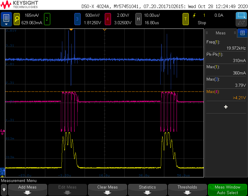
    Secondly, to find how TPS61020 got defect, you need to capture the failure waveform, such as any over voltage happens. Please share the steady state waveform at no load and normal load conditions. Please zoom in the waveform and list all four channels (Vin, Vout, SW, iL) in one picture like below picture:

    If still can't find the problem, maybe you can send 1-2 boards to me to help you debug.

  • Hello,

    Unfortulately, the pad of TPS61020 was broken from last week's 1 defect PCB. So I measured from another defect PCB. I hope that helps.

    The w/f had Vin: 3.2V and Vout: 3V wherein TPS61020 is active with load.

    Below w/f: VCC, SW, IL

    Below w/f: Vin, VCC and IL

    I am not able to attach zip file for the layout data. How can I attach zip file? Do you have personal email ID where I can send ? 

  • Hi Jain,

    So I measured from another defect PCB. 

    -> The below waveforms show the TPS61020 is still switching and working. Did you replace with a good unit on defect PCB? I'm confused.

    I'll send a friendship request on E2E. Please accept it.