This thread has been locked.

If you have a related question, please click the "Ask a related question" button in the top right corner. The newly created question will be automatically linked to this question.

TPS92515: TPS92515 debugging support

Part Number: TPS92515

Hi,

I build a board with six LED-channels using the TPS92515. I'm using analogue dimming and calculated the appropriate values by using the "TPS92515 Calculator Rev3".

I attached the sheet with my values and the schematic of one of the channels. I'm using an Arduino Mega to control the iADJ pins with a PWM signal and a low pass filter ( 33k,4u7).

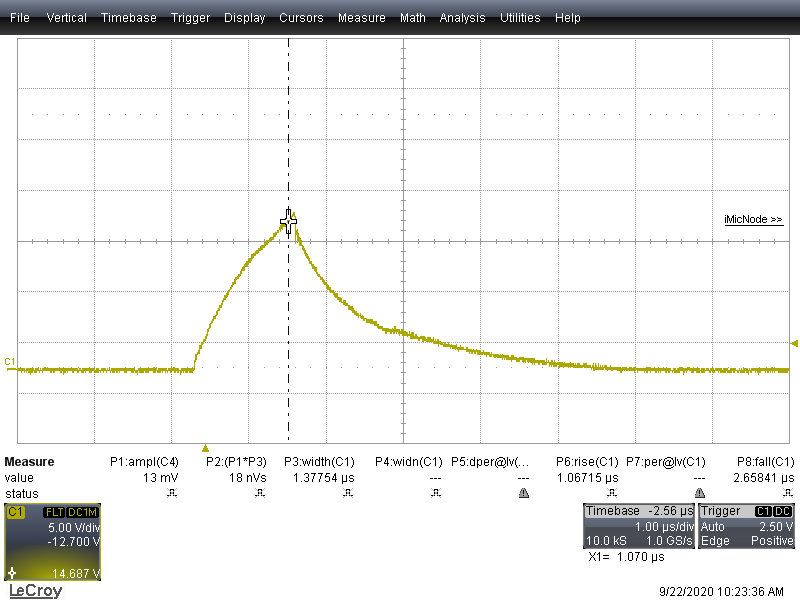
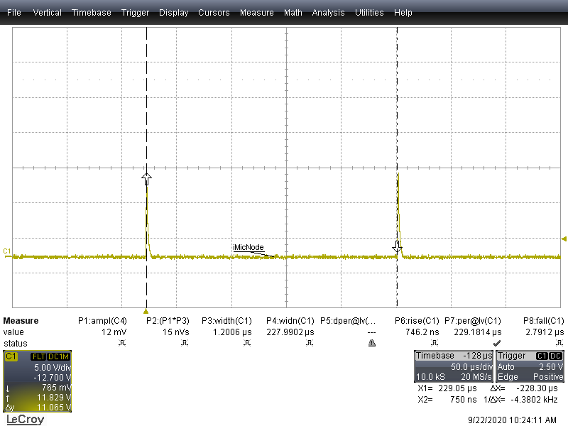
For testing i programmed a slowly rising ramp to one of the channels. As a load i use a 4ohm power resistor When i measure the voltage drop with an oscilloscope i can see spikes every 280µs but not a continuous current. I'm quite experienced hardware designer, but not in power design.

Where to start? VIN is stable and VCC output of TPS looks good and steady as well.

VanLight_LED1-LED Channel 1.pdf~TPS92515 Calculator Rev3.xls

  • Hello,

    It looks like it is running in maximum off-time mode.  C102, is that 470 nF?  Is should be 470 pF.

    It appears you have no output capacitance, this is fine.  Just note with the TPS92515 and a resistor load you can run into issues with the TPS92515 starting up.  This is because the Coff capacitor needs to be able to charge to 1.0V.  If it cannot it will go into maximum off-time.  This is common with a resistor load, expecially with an output capacitor.

    You can look at the Coff voltage to see if it is reaching 1.0V as well.

    Your design has a lot of current ripple, it will work this way as well however without an output capacitor the LEDs will see this ripple.

    Best Regards,