A related question is a question created from another question. When the related question is created, it will be automatically linked to the original question.
If you have a related question, please click the "Ask a related question" button in the top right corner. The newly created question will be automatically linked to this question.
for your 720W application would recommend a full bridge topology, could be hard switched using LM5045 or soft switched using UCC28951.
Both controllers are offering synchronous rectifier control as well; UCC28951 is using phase shifted PWM resulting in zero voltage switching over a wide output power range - resulting in less ringing, less clamping efforts, better EMI behavior and increased efficiency compared to LM5045.
Please have a look at attached apps note, best regards, Bernd
I need this referance design's tsc file for simulation at tina-ti. If you have can you please send it to me. Otherwise I need LM5045 controller's design for tina ti. I can draw the circuit as snva627 if I can get LM5045 controller's design.
w/out any calculation, just looking at your inputs about I could see:
- output voltage 60V, isn't it 12V ? - estimate 16Arms / 26Apk primary current, depending on windings ratio, so I don't get 3 Ohms sense resistor - you need to consider current sense transformer as well, please implement windings ratio to burden shunt - 720W hard switched, the design review shows Fsw 400kHz; if you could afford slightly bigger magnetics Fsw 200kHz will reduce switching losses and magnetizing losses (but rebuilding is the easiest way, and xfmr could be reused)
First of all it is not important but my name is Ali:) Furkan is helping me for my company's project.
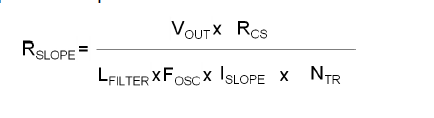
Also sorry for mis writing about Vout. Even I write this correctly the result appear wrong. In the LM5045 controller's datasheet Rcs seems like in the below
This Rcs's value seems 3 Ohm in the example project.
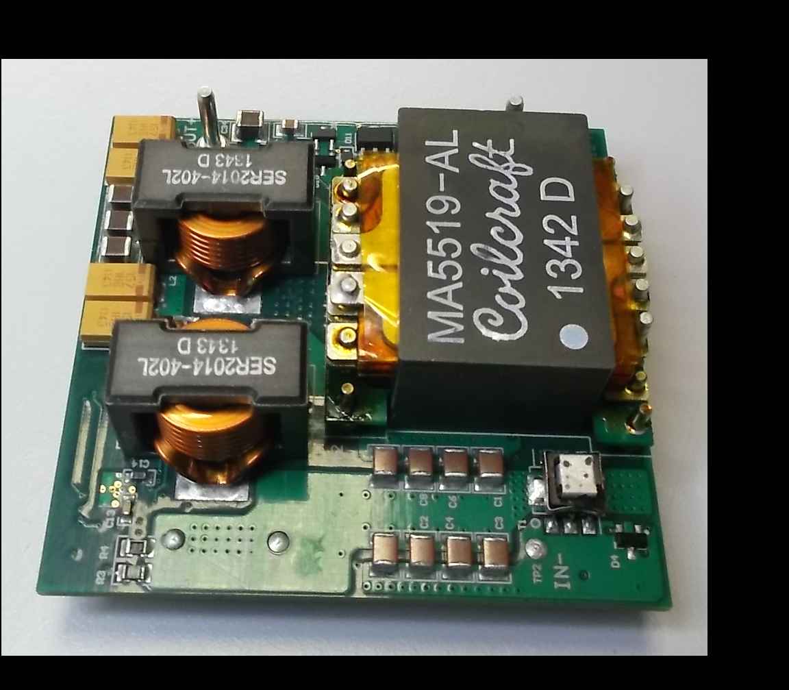
please have a look at schematics, there is a current sense transformer implemented, please see schematics T1. If you check data sheet windings ratio is 1:125.
CS at LM5045 will trip at 750mV; so for a pure resistor sensing at 26Apk (36Vin) and a margin around 20%..30% the resistor value is 750mV/32.5Amax = 23milliOhms, selected 22milliOhms. BUT: rms current of both legs is 2x 16Arms (36Vin), losses 32Arms^2 x 22milliOhms = 22.53W (!!!)
To avoid this losses a high side current sense transformer is implemented instead of low side resistor sensing. Let's calculate backwards: 750mV across burden resistor 3 Ohms results in 250mA. By windings ratio 1:125 this reflects a maximum primary current of 31.25Apk. By windings ratio 1:125 the burden resistor 3 Ohm injects a current sense resistor of 24milliOhms at bridge. So the design and my quick estimation is fairly close. (-;
Attached a analysis of your power stage at nominal input 48V, best regards, Bernd
please read my last message: the current sense resistor is 24milliOhms, there is a current sense transformer inside, just see schematics, check T1. 3 Ohms is the SECONDARY burden resistor, but power stage works across reflected PRIMARY sense resistor 24milliOhms.
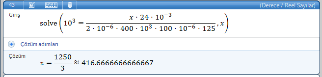
I understood you but I need to calculate Vout voltage. But when I try to calculate Vout with the formula the result is equal 416.6 V. Can you please tell me that how to calculate Vout value. I also wrote Rcs = 24*10^-3
I wrote x instead of Vout. Please help me to put this formula right way.
Please see the example at the data sheet at the bottom of page 23: output voltage 3.3V, current sense resistor 0.15 Ohms, output inductor 0.8uH, slope current 100uA, switching frequency 420kHz, windings ratio 9:1 results in slope resistor:
Rslp = (3.3V x 0.15 Ohms) / ( 0.8uH x 420kHz x 100uA x 9) = 1637 Ohms, would select 1k65.
Similar for your design:
Rslp = (12V x 24milliOhms) / (4uH x 400kHz x 100uA x 1.5) = 1200 Ohms, the design itself shows 1k.
I can't answer the question why 1k has been used instead of 1k2, this has to be answered by the designer; but we're tuning our designs on the bench, and there always might be a small difference in theory and built & tested hardware.
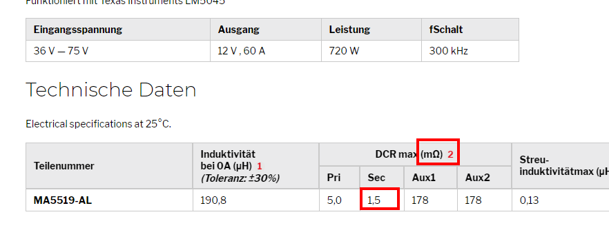
The upper windings ratio 1.5 I got from data sheet of Coilcraft MA5519-AL:
Thank you first of all. That was actually what I am asking. Do you see 1.5 ohm thing is shown as mOhm?
Also I actually want to set output voltage what ever I want. For example if I want to make output voltage 50V Can I use the same formula? If I change the place between Rslope and Vout that in the formula can I calculate Vout with the other parameters? Or Is Vout depended with another parameters? Can you help about this question?
Vout means output voltage; the design we're talking about got 12V output voltage; that's the value the prior equation is based on. I just added another example for 3.3V out of the data sheet so that you are able to follow the design procedure of our data sheet.